
User's Guide
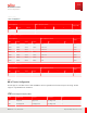
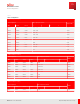
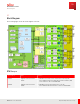
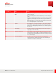
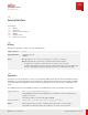
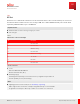
Table Of Contents
- User Guide
- Contents
- Preface
- 1 About this Guide
- 2 Overview
- 3 RU Hardware Feature
- 3.1 System Configuration
- 3.2 RU Specifications
- 3.3 Environment Specifications
- 3.4 RU Downlink/Uplink Default Parameters
- 3.5 Antenna Configuration
- 3.6 Carrier Configuration
- 3.7 Block Diagram
- 3.8 External Interface
- 3.9 TX Control Function
- 3.10 Performance Requirement
- 3.11 Mechanical Design and Other Options
- 4 Ordering Information
- 5 Installation
- 6 Operations
- 7 Maintenance and Trouble Clearing
- 8 Removal
- A References
- B ZTP Overview
- C Optical Connector Cleaning
- D Glossary
- Index

3.8.4
RET Port
This RU has one communication interface to/ from antenna line devices. The four RU antenna ports connects to
the antenna with 4.3-10 RF connectors. For steering of RET, two combined RS-485 and DC power circuit which
required by 3GPP TS 25.461, Layer 1 and AISG 2.0.
Physical interface
■ IEC 60130-9 Ed. 3.0 with screw-ring locking 8 pins, female
■ 5 A on any pin
Table 9
RET Interface Connector Pin Assign
Pin Description
1 Not connected
2 Not connected
3 RS-485 inverting
4 Not connected
5 RS-485 non-inverting
6 10…30 V DC
7 DC return
8 Not connected
Electrical interface
■ RS-485
Based on 3GPP TS 25.461/ AISG 2.0
Bit rates: 9.6/ 38.4/ 115.2 (kb/ s)
■ DC Voltage supply
DC Voltage 28.5 V (Accuracy ±1.5 V on RU connector) is supplied from pin number 6.
Current capability 0…1.0 A (normal range)
Other
■ Lightning protection circuit on RU (refer to Resistibility of Lightning)
IP65 is supported for the function of waterproofing with fitted cap or connected cable.
No guarantee for waterproof when cap or cable is loose contact or not connected.
RU Hardware Feature
External Interface
40
Release 1.0 · Issue 1, March 2021
Fujitsu and Fujitsu Customer Use Only