
User's Guide
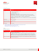
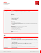
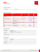
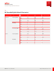
Table Of Contents
- User Guide
- Contents
- Preface
- 1 About this Guide
- 2 Overview
- 3 RU Hardware Feature
- 3.1 System Configuration
- 3.2 RU Specifications
- 3.3 Environment Specifications
- 3.4 RU Downlink/Uplink Default Parameters
- 3.5 Antenna Configuration
- 3.6 Carrier Configuration
- 3.7 Block Diagram
- 3.8 External Interface
- 3.9 TX Control Function
- 3.10 Performance Requirement
- 3.11 Mechanical Design and Other Options
- 4 Ordering Information
- 5 Installation
- 6 Operations
- 7 Maintenance and Trouble Clearing
- 8 Removal
- A References
- B ZTP Overview
- C Optical Connector Cleaning
- D Glossary
- Index

Table 1 (Cont.)
RU General Specifications
Item Specification
Interface ▪ Optical interface for ORAN (7.2x/ 10G SFP)
• SFPs are changeable in field.
• No cascade support.
▪ ANT port x 4 (4.3-10 RF connectors)
▪ RET (AISG) (8-pin circular connector conforming to IEC 60130-9 Ed. 3.0 with screw-ring locking.)
▪ LED (For indication of RU status, green: normal condition, red: failure. The eCPRI condition indicator)
▪ Debug/ Test port (RJ45 supports 100Base-T or 1GE); Only for M anufacturing use
▪ Power connector (Amphe-BTS connector series or compatible connector is used. 2 wire: −48 V DC, Return)
▪ FG (M6 bolts x 2)
Optical bit rate 10 Gb/ s (10.3125 Gb/ s)
Antenna Connector Type 4.3-10 RF Connector
Antenna Control Interface AISG
Power Supply –58…–36 V DC
1
The RU is designed to be more efficient with heat dissipation by expecting air convection.
2
TX Power down at temperature range of +45°C to +55°C.
3
The RU supports Cold start operation. (Chapter 2.7.1, 5.1.1.3)
Table 2
M easurement Function
Item Specification
VSWR alarm reporting The RU supports Voltage Standing Wave Radio (VSWR) alarm reporting on all external TX RF connections by
measuring the TX RF-signal return loss.
The VSWR must be less than 1.5 for each port under all operating and environmental conditions. When
VSWR at any port exceeds 1.5, the RU reports an alarm to the EM S and the RU stops to transmit power in
order to protect the RU from damage. The alarm indicates which port has exceeded the VSWR requirement.
Noise floor measurement The RU supports the function of measuring the Received Total Wideband Power (RTWP), when initiated by
EM S or when initiated by the DU.
RU Hardware Feature
RU Specifications
21
Release 1.0 · Issue 1, March 2021
Fujitsu and Fujitsu Customer Use Only