
Installation Instructions
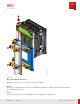
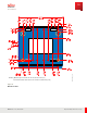
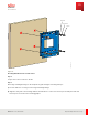
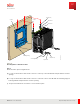
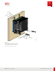
Table Of Contents
- User Guide
- Contents
- Preface
- 1 About this Guide
- 2 Overview
- 3 RU Hardware Feature
- 3.1 System Configuration
- 3.2 RU Specifications
- 3.3 Environment Specifications
- 3.4 RU Downlink/Uplink Default Parameters
- 3.5 Antenna Configuration
- 3.6 Carrier Configuration
- 3.7 Block Diagram
- 3.8 External Interface
- 3.9 TX Control Function
- 3.10 Performance Requirement
- 3.11 Mechanical Design and Other Options
- 4 Ordering Information
- 5 Installation
- 6 Operations
- 7 Maintenance and Trouble Clearing
- 8 Removal
- A References
- B ZTP Overview
- C Optical Connector Cleaning
- D Glossary
- Index

Recommended Tools:
■ 1/ 2, 7/ 16, and 11/ 16 sockets
■ 5/ 8 wrench
■ Philips screw driver
■ Power tools (optional)
Note: The screws included in the Wall M ount Kit are intended for installing the RU ont o a wood surface. To
install on ot her surfaces, for example, concret e, brick, or unistrut , the appropriate hardware mount ing anchors
must be acquired separat ely.
Note: Always ensure that the mount ing surface and anchors can wit hst and up to 240 lbs (108.862 kg) of
weight.
Step 1
Inst all the Wall M ounting Plat e to a designat ed wall location using M 10 bolt s with flat and split washers in each
of the four holes circled in the follow ing graphic to secure it in place.
Note: The wall mount plat e can be used to mark the location for the bolt s on the wall surface prior to
installation.
Installation
RU Installation
93
Release 1.0 · Issue 1, M arch 2021
Fujitsu and Fujitsu Customer Use Only