
Installation Instructions
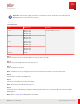
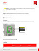
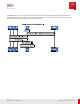
Table Of Contents
- User Guide
- Contents
- Preface
- 1 About this Guide
- 2 Overview
- 3 RU Hardware Feature
- 3.1 System Configuration
- 3.2 RU Specifications
- 3.3 Environment Specifications
- 3.4 RU Downlink/Uplink Default Parameters
- 3.5 Antenna Configuration
- 3.6 Carrier Configuration
- 3.7 Block Diagram
- 3.8 External Interface
- 3.9 TX Control Function
- 3.10 Performance Requirement
- 3.11 Mechanical Design and Other Options
- 4 Ordering Information
- 5 Installation
- 6 Operations
- 7 Maintenance and Trouble Clearing
- 8 Removal
- A References
- B ZTP Overview
- C Optical Connector Cleaning
- D Glossary
- Index

Table 33 (Cont.)
RU LED Status
RU Status
LED
Operation Fault Fronthaul
TxON Green on Red off Don't care
BLK Green blinking Red blinking Don't care
Alarm (major) Green off Red blinking Don't care
Alarm (minor) Green blinking or Green on Red blinking Don't care
L1 disconnection Don't care Don't care Green off
L1 link found (M -Plane not
found)
Don't care Don't care Green blinking
L1 & M -Plane link found Don't care Don't care Green on
RF Confirmation
The RU must be receiving configuration information from the DU during the confirmation. The met hod and
procedure of the confirmat ion are present ed by the DU vendor.
6.1.2
Complete RU Installation
Step 1
Cont act customer NOC to verify they have visibility of the RU and to verify that no active alarms are present.
Step 2
Confirm with the customer that the work is completed successfully.
Step 3
Clean up area before leaving the customer site.
✓ This task is complete.
6.1.3
Radio Commissioning
The EM S is provisioned wit h fast device discovery funct ionality and based on 3GPP st andards.
Operations
Commissioning
107
Release 1.0 · Issue 1, M arch 2021
Fujitsu and Fujitsu Customer Use Only