
Installation Instructions

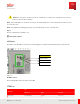
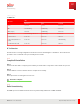
Table Of Contents
- User Guide
- Contents
- Preface
- 1 About this Guide
- 2 Overview
- 3 RU Hardware Feature
- 3.1 System Configuration
- 3.2 RU Specifications
- 3.3 Environment Specifications
- 3.4 RU Downlink/Uplink Default Parameters
- 3.5 Antenna Configuration
- 3.6 Carrier Configuration
- 3.7 Block Diagram
- 3.8 External Interface
- 3.9 TX Control Function
- 3.10 Performance Requirement
- 3.11 Mechanical Design and Other Options
- 4 Ordering Information
- 5 Installation
- 6 Operations
- 7 Maintenance and Trouble Clearing
- 8 Removal
- A References
- B ZTP Overview
- C Optical Connector Cleaning
- D Glossary
- Index

Caution: If the power to the RU is t urned off, a minimum 10-second wait is required before it is turned
back on to allow the RU to initialize.
Note: If the fault LED is on, check the connections at the RU and pow er source and optical connect ion sources
to resolve the issue.
Note: If the LED is not blinking green aft er reset, then RU st atus is not in a normal state.
Step 7
Close the maintenance window cover.
✓ This task is complete.
LED Display
The st atus of the RU LEDs, as show n in the follow ing figure, should be checked when the RU is powered up.
LED
Operational LED
Fault LED
eCPRI interface LED
Figure 31
RU LED Locations
The following table shows the st atus of the LEDs.
Table 33
RU LED Status
RU Status
LED
Operation Fault Fronthaul
Operational Green blinking Red off Don't care
Operations
Commissioning
106
Release 1.0 · Issue 1, M arch 2021
Fujitsu and Fujitsu Customer Use Only