
Installation Instructions
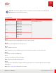
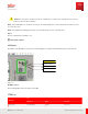
Table Of Contents
- User Guide
- Contents
- Preface
- 1 About this Guide
- 2 Overview
- 3 RU Hardware Feature
- 3.1 System Configuration
- 3.2 RU Specifications
- 3.3 Environment Specifications
- 3.4 RU Downlink/Uplink Default Parameters
- 3.5 Antenna Configuration
- 3.6 Carrier Configuration
- 3.7 Block Diagram
- 3.8 External Interface
- 3.9 TX Control Function
- 3.10 Performance Requirement
- 3.11 Mechanical Design and Other Options
- 4 Ordering Information
- 5 Installation
- 6 Operations
- 7 Maintenance and Trouble Clearing
- 8 Removal
- A References
- B ZTP Overview
- C Optical Connector Cleaning
- D Glossary
- Index

Important: If the power supply of the RU is connected in reverse, the RU does not start and is not
damaged because of the anti-reverse circuit.
Table 32
Port Output Power
Port Output power Description
Port A Band 71: 30 W
Band 29: 40 W
Band 26: 10 W
M axim um 80 W/ ant enna port
Port B Band 71: 30 W
Band 29: 40 W
Band 26: 10 W
Port C Band 71: 30 W
Band 29: 40 W
Band 26: 10 W
Port D Band 71: 30 W
Band 29: 40 W
Band 26: 10 W
DC –48V 320 W
Step 1
Remove the dust cover from the DC –48V port on the bot tom of the RU.
Step 2
Align the key in the plug and inner connector groove.
Step 3
Insert the cable into the port .
Note: The RU has reverse-polarit y protection in case the DC power leads are connected incorrectly.
Step 4
Turn the cable clockw ise unt il tight ened.
Step 5
Turn on the circuit breaker of DC power supply.
Note: Reset starts when RU det ects power on.
Step 6
Confirm the stat e of the RU by opening the maintenance window cover to check the LED color, which should be
blinking green.
Note: Refer to Table 14 for LED indicator information.
Operations
Commissioning
105
Release 1.0 · Issue 1, M arch 2021
Fujitsu and Fujitsu Customer Use Only