
User's Guide
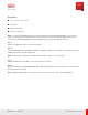
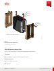
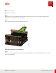
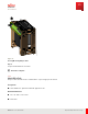
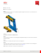

Table Of Contents
- User Guide
- Contents
- Preface
- 1 About this Guide
- 2 Overview
- 3 RU Hardware Feature
- 3.1 System Configuration
- 3.2 RU Specifications
- 3.3 Environment Specification
- 3.4 RU Downlink/Uplink Default Parameters
- 3.5 Antenna Configuration
- 3.6 Carrier Configuration
- 3.7 Block Diagram
- 3.8 External Interface
- 3.9 TX Control Function
- 3.10 Performance Requirement
- 3.11 Mechanical Design and Other Options
- 4 Ordering Information
- 5 Installation
- 6 Operations
- 7 Maintenance and Trouble Clearing
- 8 Removal
- A References
- B ZTP Overview
- C Optical Connector Cleaning
- D Glossary
- Index

■ Philips screw driver
■ Power tools (optional)
Step 1
With the RU on its back, align flat bushings with the smaller holes at the top of each L-bracket and place the
adapter plate on top with the holes also aligned.
Step 2
Insert step bushings into each of the adapter plate holes.
FNC001625_Rev_01
Figure 18
Aligning M ounting Adapter Plate and Bushings
Step 3
Secure the mounting adapter plate to the L-Brackets using M 10x30 screws with flat and split washers as shown
in the following graphic.
Installation
RU Installation
84
Release 1.0 · Issue 1, March 2021
Fujitsu and Fujitsu Customer Use Only