
User's Guide
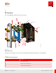
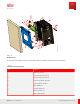
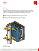
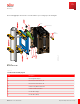
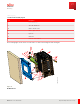
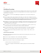
Table Of Contents
- User Guide
- Contents
- Preface
- 1 About this Guide
- 2 Overview
- 3 RU Hardware Feature
- 3.1 System Configuration
- 3.2 RU Specifications
- 3.3 Environment Specification
- 3.4 RU Downlink/Uplink Default Parameters
- 3.5 Antenna Configuration
- 3.6 Carrier Configuration
- 3.7 Block Diagram
- 3.8 External Interface
- 3.9 TX Control Function
- 3.10 Performance Requirement
- 3.11 Mechanical Design and Other Options
- 4 Ordering Information
- 5 Installation
- 6 Operations
- 7 Maintenance and Trouble Clearing
- 8 Removal
- A References
- B ZTP Overview
- C Optical Connector Cleaning
- D Glossary
- Index

5.3
Mounting
RU can be installed on a wall or pole away from the antenna. Heat generated by the RU is permitted to be
radiated to the antenna through the mounting bracket. M ounting details, for example, configuration and
position of the mounting bracket, are determined after consultation with the antenna vendor.
M ounting a RU has the following requirements:
■ Width of RU equipment, including mounting brackets, must not exceed 440 mm.
■ Pole diameter on which RU is attached must be 2 to 4.5 inches in diameter.
The following graphic shows a RU attached to a pole with a pole mounting kit.
FNC001586_Rev_01
Figure 14
Pole M ount Final Result
Installation
Mounting
75
Release 1.0 · Issue 1, March 2021
Fujitsu and Fujitsu Customer Use Only