
User's Guide


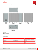
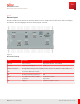


Table Of Contents
- User Guide
- Contents
- Preface
- 1 About this Guide
- 2 Overview
- 3 RU Hardware Feature
- 3.1 System Configuration
- 3.2 RU Specifications
- 3.3 Environment Specification
- 3.4 RU Downlink/Uplink Default Parameters
- 3.5 Antenna Configuration
- 3.6 Carrier Configuration
- 3.7 Block Diagram
- 3.8 External Interface
- 3.9 TX Control Function
- 3.10 Performance Requirement
- 3.11 Mechanical Design and Other Options
- 4 Ordering Information
- 5 Installation
- 6 Operations
- 7 Maintenance and Trouble Clearing
- 8 Removal
- A References
- B ZTP Overview
- C Optical Connector Cleaning
- D Glossary
- Index

3.11.2
Bottom Layout
The RU is installed on the back of the antenna, with the four 4.3-10 RF connectors at bottom of RU connecting to
the antenna. The following figure shows the bottom layout of the RU.
Port#A
DC -48V
RET
Port#B
Port#C
eCPRI
M aintenance
W indow
Port#D
Figure 11
Bottom Layout Image
Name Description Connector type
−48 V DC Power connector Amphe-BTS compatible, 10-761296-Z2S
Port A…D Antenna port A through D 4.3-10
M aintenance Window M ichigan M anufacturing International (M M I) interface, waterproof by Machine Tool Wire (M TW) cover
LED Three LEDs in M aintenance window —
Eth M ounted for measurement function RJ45
eCPRI The eCPRI format is based on ORAN
specification
FullAXS mini compatible
Cage for SFP+
RET AISG port Compliant to AISG v2.0 connector
RU Hardware Feature
Mechanical Design and Other Options
64
Release 1.0 · Issue 1, March 2021
Fujitsu and Fujitsu Customer Use Only