
User's Guide
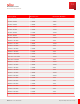
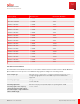
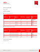
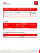

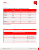
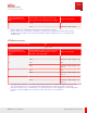
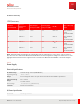
Table Of Contents
- User Guide
- Contents
- Preface
- 1 About this Guide
- 2 Overview
- 3 RU Hardware Feature
- 3.1 System Configuration
- 3.2 RU Specifications
- 3.3 Environment Specification
- 3.4 RU Downlink/Uplink Default Parameters
- 3.5 Antenna Configuration
- 3.6 Carrier Configuration
- 3.7 Block Diagram
- 3.8 External Interface
- 3.9 TX Control Function
- 3.10 Performance Requirement
- 3.11 Mechanical Design and Other Options
- 4 Ordering Information
- 5 Installation
- 6 Operations
- 7 Maintenance and Trouble Clearing
- 8 Removal
- A References
- B ZTP Overview
- C Optical Connector Cleaning
- D Glossary
- Index

BS channel bandwidth of the lowest/
highest carrier received (M Hz)
Interfering RB centre frequency offset to
the lower/ upper Base Station RF
Bandwidth edge or sub-block edge inside a
sub-block gap (kHz)
2, 3
Type of interfering signal
5 ±(350+m* 180),
m=0, 1, 2, 3, 4, 9, 14, 19, 24
5 M Hz DFT-s- OFDM NR signal, 15 kHz SCS,
1 RB
10 ±(355+m* 180),
m=0, 1, 2, 3, 4, 9, 14, 19, 24
15 ±(360+m* 180),
m=0, 1, 2, 3, 4, 9, 14, 19, 24
20 ±(350+m* 180),
m=0, 1, 2, 3, 4, 9, 14, 19, 24
1
“ x” is equal to 8 in case of 5 MHz channel bandwidth and equal to 6 otherwise.
2
Interfering signal consisting of one resource block positioned at the stated offset, the channel bandwidth of the interfering signal is
located adjacently to the lower/ upper Base Station RF Bandwidth edge or sub-block edge inside a sub-block gap.
3
The centre of the interfering RB refers to the frequency location between the two central subcarriers.
Out-of-band Blocking
(NF) NF
REF
+ 6 dB
Table 21
General Blocking
Frequency range[M Hz] Interfering Signal mean power [dBm] Type of Interfering Signal
1 ~ (FUL_low-20)
(FUL_low+20) ~ 12750
-15 CW carrier
Table 22
Blocking Performance Requirement for NR BS when Co-located with BS in Other Frequency Bands
Co-located BS type
Centre Frequency of Interfering
Signal (M Hz)
Interfering Signal mean power
(dBm)
Type of Interfering Signal
M acro GSM 850 or CDM A850 869-894 16 CW carrier
M acro PCS1900 1930-1990 16 CW carrier
WA NR Band 2 1930-1990 16 CW carrier
WA NR Band 4 2110-2155 16 CW carrier
WA NR Band 5 869-894 16 CW carrier
WA NR Band 12 729-746 16 CW carrier
WA NR Band 13 746-756 16 CW carrier
RU Hardware Feature
Performance Requirement
57
Release 1.0 · Issue 1, March 2021
Fujitsu and Fujitsu Customer Use Only