
User's Guide
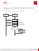
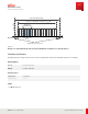
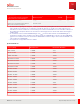
Table Of Contents
- User Guide
- Contents
- Preface
- 1 About this Guide
- 2 Overview
- 3 RU Hardware Feature
- 3.1 System Configuration
- 3.2 RU Specifications
- 3.3 Environment Specification
- 3.4 RU Downlink/Uplink Default Parameters
- 3.5 Antenna Configuration
- 3.6 Carrier Configuration
- 3.7 Block Diagram
- 3.8 External Interface
- 3.9 TX Control Function
- 3.10 Performance Requirement
- 3.11 Mechanical Design and Other Options
- 4 Ordering Information
- 5 Installation
- 6 Operations
- 7 Maintenance and Trouble Clearing
- 8 Removal
- A References
- B ZTP Overview
- C Optical Connector Cleaning
- D Glossary
- Index

When transmission carrier setting is added or changed during operation and switching of transmission mode
occurs, transmission is turned off to change drain voltage, and transmission control is performed again after
switching drain voltage.
The following flow image is sample for 3 carriers, maximum 60 W at n66.
Host system
Dual-band RU
M -Plane
established
M -Plane
established
Tx-Array-Carrier-01
message
Tx-Array-Carrier-02
message
Tx-Array-Carrier-03
message
Total 3 Carriers
Port#A
M aximum output
power=47.8dBm (60W)
n66 at port#A is 60W, so
Port#A transmit mode is
(ii)n70 + n66 :20W + 60W
Port#A n66
Port#A n66
M 66 maximum
o
utput power
< 40W ?
DL Gain: Maximum
DL Gain: Maximum
DL Gain: Maximum
output power -6dB
output power -6dB
Port#A n66
No
Yes
Switch power mode
i) -> (ii)
n70 + n66 : 20W + 60W
output power -3dB
RU Hardware Feature
TX Control Function
43
Release 1.0 · Issue 1, March 2021
Fujitsu and Fujitsu Customer Use Only