
User's Guide
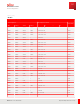

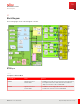
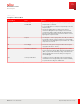
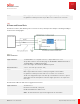
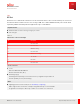
Table Of Contents
- User Guide
- Contents
- Preface
- 1 About this Guide
- 2 Overview
- 3 RU Hardware Feature
- 3.1 System Configuration
- 3.2 RU Specifications
- 3.3 Environment Specification
- 3.4 RU Downlink/Uplink Default Parameters
- 3.5 Antenna Configuration
- 3.6 Carrier Configuration
- 3.7 Block Diagram
- 3.8 External Interface
- 3.9 TX Control Function
- 3.10 Performance Requirement
- 3.11 Mechanical Design and Other Options
- 4 Ordering Information
- 5 Installation
- 6 Operations
- 7 Maintenance and Trouble Clearing
- 8 Removal
- A References
- B ZTP Overview
- C Optical Connector Cleaning
- D Glossary
- Index

3.8.5
Debug/Test Port
The RU has a RJ-45 debug/ test port for pre-deployment purposes, for example, development and manufacturing
verification.
Attention: For factory use only.
3.8.6
Maintenance Interface
A maintenance interface area is located on the bottom of the RU. This area is sealed by maintenance cover with
protection against water ingress. The maintenance cover can be opened manually without a tool.
The RU maintenance cover has three LEDs that indicate the status of the RU for example, operation, failure
(machine status) and eCPRI link.
■ One Fault, Red color
■ One Operational, Green color
■ One Interfaces, Green color (one corresponding to eCPRI port)
The software controls the on/ off and blinking LEDs according to the status of the RU.
Table 11
RU Status by LED Combination
RU status
LED
Operation Fault Fronthaul
Operational Green blinking Red off Don’t care
Transmitter On Green on Red off Don’t care
Blocking Green blinking Red blinking Don’t care
M ajor Alarm Green off Red blinking Don’t care
Critical Alarm Green off Red on Don’t care
M inor Alarm Green blinking
or
Green on
Red blinking Don’t care
L1 disconnection Don’t care Don’t care Green off
RU Hardware Feature
External Interface
39
Release 1.0 · Issue 1, March 2021
Fujitsu and Fujitsu Customer Use Only