
User's Guide

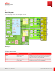
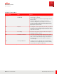
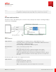
Table Of Contents
- User Guide
- Contents
- Preface
- 1 About this Guide
- 2 Overview
- 3 RU Hardware Feature
- 3.1 System Configuration
- 3.2 RU Specifications
- 3.3 Environment Specification
- 3.4 RU Downlink/Uplink Default Parameters
- 3.5 Antenna Configuration
- 3.6 Carrier Configuration
- 3.7 Block Diagram
- 3.8 External Interface
- 3.9 TX Control Function
- 3.10 Performance Requirement
- 3.11 Mechanical Design and Other Options
- 4 Ordering Information
- 5 Installation
- 6 Operations
- 7 Maintenance and Trouble Clearing
- 8 Removal
- A References
- B ZTP Overview
- C Optical Connector Cleaning
- D Glossary
- Index

3.7
Block Diagram
The following figure shows a block diagram of the RU.
Figure 6
Block Diagram
Table 9
Description of Function Block
Function Block Name Function
DPDC#A Digital Pre-Distortion
Central unit#A
▪ DPDC#A monitors and controls each interface in the RU by LLB. It
has a Digital Pre-Distortion (DPD) and Crest Factor Reduction
(CFR) control function for PA of n70n66-RF#A.
DPDC#B Digital Pre-Distortion
Central unit#B
▪ DPDC#B has a Power Supply (PS) function for the RU. It has a DPD
and CFR control function for PA of n70n66-RF#B.
RU Hardware Feature
Block Diagram
34
Release 1.0 · Issue 1, March 2021
Fujitsu and Fujitsu Customer Use Only