
User's Guide
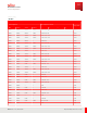

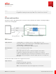
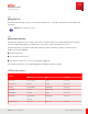
Table Of Contents
- User Guide
- Contents
- Preface
- 1 About this Guide
- 2 Overview
- 3 RU Hardware Feature
- 3.1 System Configuration
- 3.2 RU Specifications
- 3.3 Environment Specification
- 3.4 RU Downlink/Uplink Default Parameters
- 3.5 Antenna Configuration
- 3.6 Carrier Configuration
- 3.7 Block Diagram
- 3.8 External Interface
- 3.9 TX Control Function
- 3.10 Performance Requirement
- 3.11 Mechanical Design and Other Options
- 4 Ordering Information
- 5 Installation
- 6 Operations
- 7 Maintenance and Trouble Clearing
- 8 Removal
- A References
- B ZTP Overview
- C Optical Connector Cleaning
- D Glossary
- Index

3.6
Carrier Configuration
The RU supports the 5G-NR carrier configuration as shown in the following table.
Each band has the following available carrier and maximum transmit power:
n70: Up to 2 carriers, 40 W/ port
n66: Up to 3 carriers, 60 W/ port
Note: RU supports the total maximum of 4 carriers and 80 W per 1 port (total 320 W) as the possible
combination of carrier and maximum transmit power.
Table 7
2 W/ M Hz
n70 (M ax. 40 W/ antenna, up to 2 Carriers)
Carrier Configuration M ax. output power/ antenna
Output (4ANT)
Occupied
Bandwidth
(OBW )
Carrier 1 Carrier 2 1 2 3 4
20 MHz 20 MHz — 40 W 160 W
20 MHz 15 MHz 5 M Hz 30 W + 10 W 160 W
20 MHz 10 MHz 10 MHz 20 W + 20 W 160 W
15 MHz 15 MHz — 30 W 120 W
15 MHz 10 MHz 5 M Hz 20 W + 10 W 120 W
10 MHz 10 MHz — 20 W 80 W
10 MHz 5 M Hz 5 M Hz 10 W + 10 W 80 W
5 M Hz 5 M Hz — 10 W 40 W
Table 8
1 W/ M Hz
n66 (M ax 60 W , up to 3 carriers)
Carrier Configuration M ax. output power/ antenna
Output (4ANT)
OBW Carrier 1 Carrier 2 Carrier 3 1 2 3 4
60 MHz 20 MHz 20 MHz 20 MHz 20 W + 20 W + 20 W 240 W
55 MHz 20 MHz 20 MHz 15 MHz 20 W + 20 W + 15 W 220 W
50 MHz 20 MHz 20 MHz 10 MHz 20 W + 20 W + 10 W 200 W
RU Hardware Feature
Carrier Configuration
31
Release 1.0 · Issue 1, March 2021
Fujitsu and Fujitsu Customer Use Only