
User's Guide
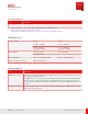
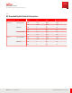
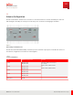
Table Of Contents
- User Guide
- Contents
- Preface
- 1 About this Guide
- 2 Overview
- 3 RU Hardware Feature
- 3.1 System Configuration
- 3.2 RU Specifications
- 3.3 Environment Specification
- 3.4 RU Downlink/Uplink Default Parameters
- 3.5 Antenna Configuration
- 3.6 Carrier Configuration
- 3.7 Block Diagram
- 3.8 External Interface
- 3.9 TX Control Function
- 3.10 Performance Requirement
- 3.11 Mechanical Design and Other Options
- 4 Ordering Information
- 5 Installation
- 6 Operations
- 7 Maintenance and Trouble Clearing
- 8 Removal
- A References
- B ZTP Overview
- C Optical Connector Cleaning
- D Glossary
- Index

3.5
Antenna Configuration
The RU communication interface has connections to/ from antenna devices. The RU has 4 RF ports, with n70,
n66 sharing the same RF ports. The layout of antenna ports is shown the following figure and table.
Port#A
DC –48V
RET
eCPRI
Port#C
Port#B Port#D
Figure 5
Layout Image of Antenna Ports
The RU can transmit maximum 80 W per antenna port, the maximum output power is 320 W. The features of
the antenna configuration are listed in the following table.
Table 6
Antenna Configuration
Port M aximum output power Remarks
Port#1 Band 70: 40 W
Band 66: 60 W
M aximum 80 W per antenna port.
For example,
Band 70: 40 W + Band 66: 40 W
or
Band 70: 20 W + Band 66: 60 W
Port#2 Band 70: 40 W
Band 66: 60 W
Port#3 Band 70: 40 W
Band 66: 60 W
Port#4 Band 70: 40 W
Band 66: 60 W
Total power 320 W —
RU Hardware Feature
Antenna Configuration
30
Release 1.0 · Issue 1, March 2021
Fujitsu and Fujitsu Customer Use Only