
User's Guide
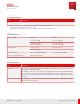
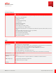
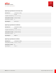
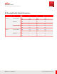
Table Of Contents
- User Guide
- Contents
- Preface
- 1 About this Guide
- 2 Overview
- 3 RU Hardware Feature
- 3.1 System Configuration
- 3.2 RU Specifications
- 3.3 Environment Specification
- 3.4 RU Downlink/Uplink Default Parameters
- 3.5 Antenna Configuration
- 3.6 Carrier Configuration
- 3.7 Block Diagram
- 3.8 External Interface
- 3.9 TX Control Function
- 3.10 Performance Requirement
- 3.11 Mechanical Design and Other Options
- 4 Ordering Information
- 5 Installation
- 6 Operations
- 7 Maintenance and Trouble Clearing
- 8 Removal
- A References
- B ZTP Overview
- C Optical Connector Cleaning
- D Glossary
- Index

RF Common Mode
Test standard 3GPP 38.113
IEC 61000-4-6 Level 2
150 kHz…80 M Hz 3 Vrms
Performance criteria A
Injected port Power port, RET port
Resistability of Lightning
DC Pow er Port
IEC61000-4-5
(Combination wave)
Level 4
L-L (Differential mode) ±2 kV(1.2/ 50 μs)
L-FG (Common mode) ±4 kV(1.2/ 50 μs)
Performance criteria B
Injected port Power port
RET Port
IEC61000-4-5
(Combination wave)
Level 4
L-L (Differential
mode):
±2 kV(10/ 700 μs)
L-FG (Common mode) ±4 kV(10/ 700 μs)
Performance criteria B
Injected port RET port
RF Port
IEC61000-4-5
(Combination wave)
Level 4
L-FG (Common mode) ±20 kV (1.2/ 50 μs)
Performance criteria B
Injected port RF port
RU Hardware Feature
Environment Specification
27
Release 1.0 · Issue 1, March 2021
Fujitsu and Fujitsu Customer Use Only