
User Manual

29
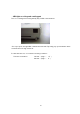
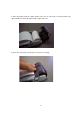
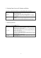
9. Interface Connector Connection (RS-232C Connection Part)
1) Part No.: RL01-R12P (Japan Aviation Electronics Industry, Ltd.) or equivalent
2) Signal pin assignment
No. Signal name Direction Function
1 GND --------- Signal ground
2 RxD Input Receive data
3 TxD Output Send data
4 DTR Output Data terminal ready
5 DSR Input Data set ready
6-12 N.C. -------- Not connected
Note) ・Input and output are defined from the printer side.
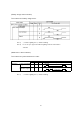
・For pin number, refer to the figure below.
3) Connector model No.: RL01-P12S-C (Japan Aviation Electronics Industry, Ltd.) or
equivalent
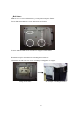
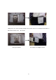
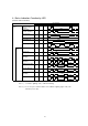
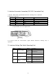
10. Interface Setting (Dip Switch Operating Part)
Bit No. Function Setting Description
OFF Wireless interface
1 Interface setting
ON Wired interface
OFF Teletype protocol mode
2 Communication mode
ON Packet communication mode
OFF
3 Reserve
ON
OFF Printer execution mode
4
Start program
selection
ON Program download mode