
Installation Guide
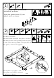

3
6/14
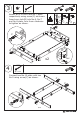
4
I II III
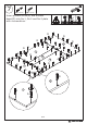
x2
C x 8
4 x 45mm
C
C
C
C
C
C
C
C
C
C
4
7
8
6
5
5
5
5
8
4
C
C
C
C
C
C
B
B
B
B
B
B
B
B
B
B
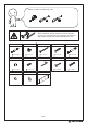
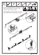
B x 16
15 x 9 mm
C x 8
4 x 45mm
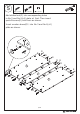
180°
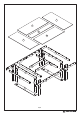
Attach No.5 to No.6 and No.7 plate
respectively using screw(C) as shown.
Insert cam lock(B) into No.6, No.7
and No.8 plate, turn them clockwise
to tighten as shown.
Connect two No.10 plate with two
No.9 using screw(C) as shown.