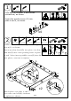
Conference table Version:08/29/2022 1/14
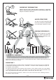
IMPORTANT INFORMATION! please read the entire manual before starting to assemble and/or using this product.follow the manual thoroughly and keep it for further reference. AVOID SCRATCHES! In order to avoid scratching this furnuture should be assembled on a soft layer-could be a rug. IMPROVE EFFICIENCY ! Try to find a partner to install with you, which can speed up the installation efficiency and shorten the time. ANTI-TOPPLE WARNING ! Overturned furniture can cause serious or fatal crush injuries.
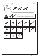
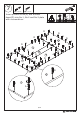
Please prepare the following tools When installing, please carefully confirm whether each screw corresponds to the manual, accessories with similar shapes can be distinguished by size A x 66 6 x 35 mm F x 14 6 x 10 mm L x 16 B x 80 C x 24 15 x 9 mm 4 x 45 mm G x 16 Hx1 6 x 14 mm M x 16 Nx2 3/14 D x 54 8 x 30 mm E x 14 6 x 50 mm Jx8 K x 16 4 x 25 mm 6 x 30 mm
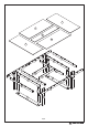
1 2 3 2 1 5 13 11 4 7 12 10 9 5 6 9 6 4 8 10 11 13 7 8 5 4/14 12 5
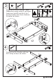
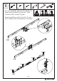
A x 16 1 Dx8 Ø 6 x 35 mm Ø 8 x 30 mm Cam Bolt (A) to plate 5 with across screwdriver, as shown. Insert the wooden tenon (D) into plate 4 and 5, as shown. A D D 5 A x4 2 Bx4 Cx8 Dx8 Ex4 Fx4 Ø 15 x 9 mm Ø 4 x 45mm Ø 8 x 30 mm Ø 6 x 50 mm Ø 6 x 10 mm Connect Plate 6 and 7 with plate 8 using screw(C) as shown. Insert wooden dowel(D) into plate 4 at first. Add nut(F) into corresponding holes in plate I II 6 and 7,then insert quickfit screw(E) into the two plates, turn nut to tighten.
3 B x 16 Cx8 15 x 9 mm 4 x 45mm Attach No.5 to No.6 and No.7 plate respectively using screw(C) as shown. Insert cam lock(B) into No.6, No.7 and No.8 plate, turn them clockwise to tighten as shown. I C 4 C 5 6 B 4 B B B C 7 C 5 III C B 5 C II 5 8 B B B 8 x2 B 180° B Cx8 4 4 x 45mm Connect two No.10 plate with two No.9 using screw(C) as shown.
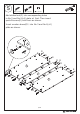
5 E x 10 D x 22 8 x 30 mm F x 10 6 x 50 mm 6 x 10 mm Add slotted nut(F) into corresponding holes in No.3 and No.2(x2) plate at first. Then insert quickfit screw(E) into them as shown. Insert wooden dowel(D)into No.3 and No.2(x2) plate as shown.
B x 10 6 15 x 9 mm Connect two No.1 plate with the component and turn cam lock(B) clockwise to tighten as shown.
A x 34 7 D x 20 6 x 35 mm 8 x 30 mm Insert quickfit screw(A) and wooden dowel(D) into No.1, No.2 and No.3 plate with a screwdriver.
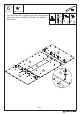
8 A x 16 6 x 35 mm G x 16 Jx8 6 x 14 mm 4 x 25 mm Nx2 Fix iron sheet(N) with No.12 and No.13 plate using screw(G) as shown. Then reinforce with screw(J) again. Insert quickfit screw(A) into No.12 and No.13 plate with a screwdriver as shown.
B x 16 9 15 x 9 mm Connect No.11 with No.12 and No.13 plate, then turn cam lock(B) clockwise to tighten as shown.
10 B x 28 15 x 9 mm Connect the two assembled component and turn cam lock(B) clockwise to tighten as shown.
11 Bx6 15 x 9 mm Attach the assembled component in step 3 to the unit, then turn cam lock(B) clockwise to tighten as shown.
K x 16 12 L x 16 M x 16 6 x 30 mm Fix No.5 with No.12 and No.13 plate using washer(M,L) and screw(K) as shown.