
Installation Guide

A
A
A
A
L
L
L
T
T
H
B
B
B
B
B
L
17
18
15/20
B x 4
H x 1
A x 4
DR
DR
x
1
DL
DL
x 1
4 x 12mm
T x 2
L x 4
4 x 30 mm
3 x 12mm
R x 4
R
R
R
R
6 x 35mm
15 x 10mm
23
23
24
22
22
22
22
21
21
25
T
L
DR
R
180°
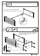
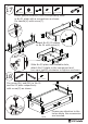
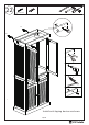
Insert quickfit screw(A) into corresponding holes
in No.21 plate with a screwdriver as shown.
Fix handle(H) with screw(T).
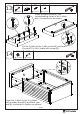
Attach No.22,23 plates
to No.24 with screw(L).
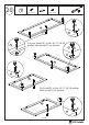
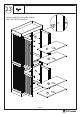
Fix runner(DL) and(DR) to No.22
and No.23 plate respectively
with screw(R) as shown.
Please pay attention to the
holes where the accessories
are inserted.
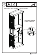
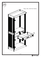
Slide No.25 plate into available slots,
attach No.21 plate to the component and
turn cam lock(B) clockwise to tighten as shown.