Sideboard Version:10/20/2022 1/19
IMPORTANT INFORMATION! please read the entire manual before starting to assemble and/or using this product.follow the manual thoroughly and keep it for further reference. AVOID SCRATCHES! In order to avoid scratching this furnuture should be assembled on a soft layer-could be a rug. IMPROVE EFFICIENCY ! Try to find a partner to install with you, which can speed up the installation efficiency and shorten the time. ANTI-TOPPLE WARNING ! Overturned furniture can cause serious or fatal crush injuries.
1 19 18 17 19 4 8 5 7 6 8 3 2 9 11 12 16 15 10 13 14 14 3/19 13
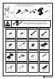
Please prepare the following tools When installing, please carefully confirm whether each screw corresponds to the manual, accessories with similar shapes can be distinguished by size A x 70 B x 16 M3.5 x 14 mm M4 x 16 mm Ex4 M4 x 18 mm Jx4 Cx8 4 x 35 mm F x 17 4 x 30 mm G x 17 6 x 28 mm Hx4 15 x 10 mm 35 mm Lx8 Kx4 Mx2 4.
/19
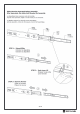
1 Fx4 Ø6 x 28mm Insert quickfit screw(F) into corresponding holes is No.5 and No.6 plate with a screwdriver as shown. F 6 F F F F 2 5 Rx2 Ax6 350mm M3.5*14mm R2 Separate glide into two parts at first. A A A A R2 R2 A A 6 A R2 Fix slide rail(R2) to No.5 and No.6 respectively with screw(A) as shown.
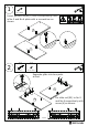
3 Kx2 Ax4 M3.5 x 14mm Fix part(K) to No.7 plate with screw(A) as shown. A A K A K 7 4 Gx4 Ø15 x 10mm Connect No.5 and No.6 plate with No.7,and turn cam lock(G) in No.7 plate clockwise to tighten as shown.
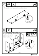
5 Slide No.18 plate into available slots as shown. 18 6 7 5 6 Fx8 Ø6 x 28mm Insert quickfit screw(F) into corresponding holes in No.1 plate with a screwdriver as shown.
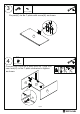
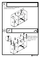
Ax4 Kx2 7 M3.5 x 14mm Fix part(K) to No.1 plate with screw(A) as shown. A K 1 A A K K 8 A Gx8 Ø15 x 10mm Attach No.1 plate to No.3, No.6, No.5 and No.4 plate,and turn cam lock(G) in No.3,6,5,4 plates clockwise to tighten as shown.
9 Slide No.19 and No.17 plate into available slots as shown. 19 17 3 6 7 19 5 1 4 10 Cx8 Ø4 x 35mm C C C C C C 2 2 C C 6 C 5 4 10/19 3 Attach No.2 plate to No.3, No,6, No.5 and No.4 plate, and fix with screw(C) as shown.
Px1 Nx4 B x 16 Ax4 180mm 180mm M4 x 16mm M3.5 x 14mm B B N B A N B B B N 12 B B N B P A B 2 B B B N B 2 Fix leg(N) to No.2 plate with screw(B) as shown. Fix leg support(P) to No.2 plate with screw(A) as shown. Lx8 Ø4.9 x 16mm 5 4 L L 3 L L 6 Insert part(L) into corresponding holes in No.3, No,6, No.5 and No.4 plate as shown.
13 4 5 8 6 3 8 Place No.8 shelf in as shown. 14 Hx4 Ax8 M3.5 x14 Ø35 A H Ø35 Ø35 A H A A H 13 J Fix hinge(H) to No.13 plate with screw(A) as shown.
Jx4 15 Ax8 M3.5 x14 Ø35 A A A A J J H Ø35 Ø35 Fix hinge(J) to No.14 plate with screw(A) as shown. J A A 14 J x2 16 Ax8 M3.5 x14 A A A A A 13 3 A A Attach No.13 plate to No.3 by fixing hinge with screw(A) as shown.
17 Ax8 M3.5 x14 J H Ø35 Ø35 Attach No.14 plate to No.6 by fixing hinge with screw(A) as shown. 6 A A 14 A A A 18 A A Ax8 M3.5 x14 J H Ø35 Ø35 Attach No.14 plate to No.5 by fixing hinge with screw(A) as shown.
Ax8 19 M3.5 x14 Attach No.13 plate to No.4 by fixing hinge with screw(A) as shown. A A 4 13 A A A A Rx2 20 A Ax4 R1 350mm Ø3.5*14mm Fix runner(R1) to No.10 and No.11 plate with screw(A) as shown.
21 Dx6 Ø4x 30mm Attach No.10, No.12 and No.11 to No.9 plate, and fix with screw(D) as shown. 11 D 12 9 D 10 D D D 9 10 D D 22 Slide No.16 plate into available slots as shown.
Fx5 23 F Ø6 x 28mm F Insert quickfit screw(F) into No.15 plate with a screwdriver as shown. F 15 F F A 24 Mx2 Ex4 Gx5 64MM M4 x 18mm Ø15 x 10mm Attach No.15 to No.10, No.12 and No.11 , and turn cam lock(G) in No.10,12,11 plates clockwise to tighten as shown. M E G E E 15 11 M E M E E 12 16 9 G G G 10 Fix handle(M) to No.15 plate using screw(E) as shown.
25 Align rails, slide the drawer. Qx1 26 Install anti-tipping device(Q) as shown.
27 19/19