
Operation Manual


PAG.
13
rev 1.1
ENGLISH
PANEL & REMOTE CONTROL DESCRIPTION
1. PANEL & REMOTE CONTROL DESCRIPTION
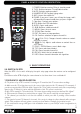
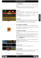
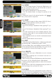
1.1. FRONT PANEL DESCRIPTION
1. POWER: Switches the receiver on, or enters standby mode.
2. LOCK LED: Indicates a suffi cient signal level at the IF IN input.
3. POWER LED: Indicates that the mains voltage (230 VAC) is available.
4. DISPLAY: 4 Digits to display the program numbers.
5. IR-SENSOR: Reception sensor for the IR remote control signals.
6. CH+/-: These buttons allow changing the current channel.
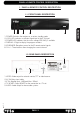
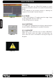
1.2. REAR PANEL DESCRIPTION
1. VIDEO: Video output for external monitor, TFT or video beamer.
2. AC IN: Mains input cable.
3. IF IN: Satellite input. LNB load: Max. 300mA
4. TV SCART: Output SCART for the connection to a TV set.
5. AUDIO: Audio output for home audio systems.
1
32
5
6
2
3
4
4
1
5