
Operation Manual

User’s manual · MAX IPS100
Technical changes and mistakes reserve - 3 - MAX IPS100 Version en_1.0 FTE Maximal
0. Control elements and connections
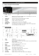
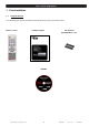
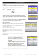
0.1. Receiver front panel
1 2 3 4 5 6 7
1 POWER: Switches the receiver ON or in Standby mode. For total switching off, use the main
switch at the back side of the receiver.
2 POWER LED: Indicates that the mains voltage (90-230 VAC) is available.
3 LOCK LED: Indicates a sufficient signal level at the input
4 DISPLAY: 4 Digits to display the program numbers.
5 IR-SENSOR: Reception sensor for the IR remote control signals
6 FRONT COVER: Opening front door, you can access to conditional access system.
7 BUTTONS: These buttons allow controlling the main functions of the receiver, and provide the
same functionality as the remote control ones.
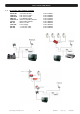
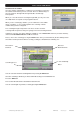
0.2. Receiver back panel
1 2 3 4 5 6
7 8 9 10 11
1 IF IN: Satellite input.
2 IF OUT: Satellite output for cascading to other devices.
Note: The operation of another receiver at the same time is only possible with limited
channel selection.
3 ETHERNET: Network connection of the receiver.
4 RS-232: Serial port to update the firmware of the receiver
5 AC IN: Power cord 230VAC/50Hz.
6 POWER ON/OFF: Main switch to switch off totally the receiver
7 AUDIO: Audio output for home audio systems
8 VIDEO: Video output for external monitor, TFT or video beamer
9 COAXIAL S/PDIF: Coaxial output for digital audio (AC3)
10 TV SCART: SCART output for connecting one TV set
11 VCR SCART: SCART connector for video recorder, DVD recorder or DVD player