
Operation Manual


User’s manual · I-PVR T152 CI HDMI
Technical changes and mistakes reserve - 4 - I-PVR T152 CI HDMI Version en_1.0 FTE Maximal
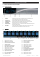
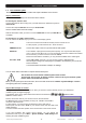
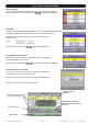
0.3. Receiver back panel
1 2 3 4 5 6 7 8 9
10 11 12 13 14 15
1 POWER ON/OFF: Main switch to switch off totally the receiver.
2 AC IN: Power cord 230VAC/50Hz.
3 ANTENNA IN 2: Input of the second digital tuner, it must be connected to LOOP OUT 1
4 ANTENNA IN 1: Input of the first digital tuner
5 ANT IN: Antenna input for analogue signals, it must be connected to LOOP OUT 2
6 ETHERNET: Network connection of the receiver.
7 RS-232: Serial port to update the firmware of the receiver.
8 OPTICAL S/PDIF: Optical output for digital audio (AC3)
9 HDMI: Video & Audio Output to connect the TV.
10 LOOP OUT 2: Output from second digital tuner, it must be connected to ANT IN
11 LOOP OUT 1: Output from first digital tuner, please connect to ANTENNA IN 2
12 TO TV: Modulator output to connect one TV set. Audio signal is available in Mono.
13 TV SCART: SCART output for connecting one TV set
14 VCR SCART: SCART connector for video recorder, DVD recorder or DVD player.
15 COAXIAL S/PDIF: Coaxial output for digital audio (AC3)