ETWF 310 USER’S MANUAL
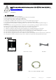
User’s manual · ETWF 310 NOTE: This user’s guide is adapted to software version v.1.26 of ETWF 310 dated 25/11/2011. For future software updates, you can download the user’s guide from the following website: http://www.ftemaximal.com/ Chapter 1. Installation. 1.1. Safety Measures 1.- Never place the device next to hot sources. 2.- Never undergo the device to temperatures that exceed its level of operation. 3.- Never expose the device to leakings nor spatterings. 4.
User’s manual · ETWF 310 1.3. Description and connections The module ETWF 310 is used for the reception of two base band channels (A/V). Each module allows the modulation of both base band input signals in a multiplex DVB-T (COFDM). A feature of this equipment is its modulator in Vestigial Side Band (or VSB). This modulation can be used to distribute adjacent channels in one distribution without any intermodulation problem.
User’s manual · ETWF 310 1.4. Programming ETWF 310 has two ethernet connectors. In order to make the programming of the module you have to connect the corresponding programmer to PRO 201 connector. You can make the programming through the PRO 201 programmer and also through the mediaMAX EVO and mediaMAX MINI field strength meter. 1.4.1.
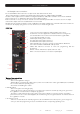
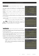
User’s manual · ETWF 310 1. Select Device The field strength meter allows carrying out the programming of one or several modules from an only modules. Without interconnection of modules. An only module connected Interconnection of several modules, you can select which module you wish to program. 2. Device Status In the option “Device Status” are specified the main parameters of the module at this moment. - Front End: It indicates whether the module is hooked or without signal.
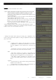
User’s manual · ETWF 310 4. Modulator Set Up This option allows configuring the DVB-T/DVB-H modulator of the device. - Bandwidth: Selection of the Bandwidth of the modulated signal: 8 MHz, 7 MHz, 6 MHz and 5MHz. The 5 MHz option is only supported by DVB-H standard. - FFT Mode: 8K, 4K and 2k. The 4k option is only supported by DVB-H standard. -Spectrum inversion: Activate or deactivate the spectrum reverse in the modulation.
User’s manual · ETWF 310 6. System This option provides information of the module. - System logfile: In this field are indicated the registered events in the module. - Read log: It allows reading the registered events in the module. - Clear log: It allows deleting all events stored until this moment. - Export log to USB: It allows you to export all events registered to the connected USB device.
User’s manual · ETWF 310 - Configure all devices: - Input values to all devices: It allows copying the current input configuration in all the interconnected modules. - Modulator values to all devices: It allows copying the configuration of the current modulator in all the interconnected modules. - Output values to all devices: It allows copying the current output configuration in all the interconnected modules.
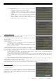
User’s manual · ETWF 310 Adding services: 1. Select “Service to add” option 2. Select one of the transponder services you want to add. 3. Once you have chosen the service, select the “Add/Remove” button to include the service in the multiplex. Note: It is not recommended to exceed the 85% of the maximum capacity of the multiplex due to the possible variability of the bits rate of the inputs services.
User’s manual · ETWF 310 - Remove all services: It allows removing all the services included in the multiplex. - Modify LCN: The LNC function allows assigning automatically a predetermined position to each one of the services of the multiplex. This function will allow the users who have a receiver with LNC support to make the ordination of channels automatically.
User’s manual · ETWF 310 Next it is attached the identification table (NID/ONID) of the main satellites. You will be able to find more information in the law ETSI TR 101 162 v1.2.1. Satellite Hotbird 13ºE (Eutelsat 13ºE) Astra 19.
User’s manual · ETWF 310 Terrestrial modulation (Out Terr) These options allow configuring the DVB-T/DVB-H modulator of the device. ETWF310 *Out Terr Modulation: 16 >Invert: No GI: 1/32 - Modulation: Output modulation format: QPSK (4 QAM), 16 QAM, 64 QAM. - Invert (Spectrum inversion): Activate or deactivate the spectrum reverse in the modulation. - GI (Guard interval): Allows selecting the guard interval of the modulation: 1/4, 1/8, 1/16 and 1/32.
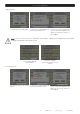
User’s manual · ETWF 310 - Write to module: It loads in the module one of the configurations previously saved in the memory of the programmer. The steps to make a correct configuration of the headend are specified below: ETWF310 > *Write to Module * *Read from Module* 1. Select the option “Write to module” through Up/Down buttons. Press OK to continue ETWF310 CFG:00 Enc.Bitrate:6750 Vid.Resol:720x480 Output Freq:682000 2. Select the position of the “CFG” memory that you wish to copy in the module.
User’s manual · ETWF 310 - Delete Services ETWF310 BW usage 032% >Delete services Add services ETWF310 Output 032% PID:00256 TR391 CH1# -Rem --All 1. Select the option “Delete services” through Up/Down buttons. Press OK to continue. 2. Select the service you want to delete with the Left/Right keys. Then press OK over “-Rem” in order to remove it, or press OK over “--All” in order to delete all the services of the multiplex. ETWF310 Operation finish 3.
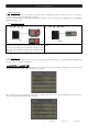
User’s manual · ETWF 310 1.5. Accessories and example of installation Example of installation The installation is formed by 6 TSF 310 and two ETWF 310 that will make possible to tune up to 6 different transponders (TSF) and moreover the reception of up to 4 base band channels (ETWF 310). In both cases the channels will be modulated in DVB-T and distributed through the installation.
User’s manual · ETWF 310 Chapter 2. Technical features Ref.
User’s manual · ETWF 310 ATACHMENT I Depending on the configured parameters we are going to obtain one particular channel capacity (output useful bit rate).
User’s manual · ETWF 310 Useful channel capacity (8 MHz) Modulation QPSK 16-QAM 64-QAM FEC codification 1/2 2/3 3/4 5/6 7/8 1/2 2/3 3/4 5/6 7/8 1/2 2/3 3/4 5/6 7/8 Guad Interval 1/4 4.976 6.635 7.465 8.294 8.709 9.953 13.271 14.929 16.588 17.418 14.929 19.906 22.394 24.882 26.126 1/8 5.529 7.373 8.294 9.216 9.676 11.059 14.745 16.588 18.431 19.353 16.588 22.118 24.882 27.647 29.029 1/4 4.354 5.806 6.532 7.257 7.62 8.709 11.612 13.063 14.515 15.24 13.063 17.418 19.595 21.772 22.861 1/8 4.838 6.
ESPAÑA Mogoda, 110 Pol. Industrial Can Salvatella 08210 Barberà del Vallès (Barcelona) España Tel. 00 34 93 729 27 00 Fax. 00 34 93 729 30 73 ftemaximal@ftemaximal.com www.ftemaximal.com FRANCE 16 ZAE Les Mouilles 74570 Groisy Tel. 00 33 450 68 80 17 Fax. 00 33 450 68 84 68 sav@ftemaximal.fr www.ftemaximal.com ITALIA Via Edison, 29 42040 Calerno di Sant’Ilario d’Enza (RE) Tel. 00 39 05 22 90 97 01 Fax. 00 39 05 22 90 97 48 fte@fte.it www.ftemaximal.