
Datasheet


© Copyright 2005-2011 Future Technology Devices International Ltd
26
Document Reference No.: FT_000051
UM232R USB - Serial UART Development Module
Datasheet Version 1.1
Clearance No.: FTDI# 125
Appendix A – List of Tables and Figures
List of Tables
Table 4.1Module Pin Out Description .......................................................................... 9
Table 4.2 Jumper J1 Pin Description ........................................................................... 9
Table 4.3 Jumper J2 Pin Description ........................................................................... 9
Table 4.4 CBUS Signal Options ................................................................................. 10
Table 6.1 Absolute Maximum Ratings ....................................................................... 12
Table 6.2 Operating Voltage and Current .................................................................. 12
Table 6.3 UART and CBUS I/O Pin Characteristics (VCCIO = 5.0V, Standard Drive Level)
................................................................................................................................. 13
Table 6.4 UART and CBUS I/O Pin Characteristics (VCCIO = 3.3V, Standard Drive Level)
................................................................................................................................. 13
Table 6.5 UART and CBUS I/O Pin Characteristics (VCCIO = 2.8V, Standard Drive Level)
................................................................................................................................. 13
Table 6.6 UART and CBUS I/O Pin Characteristics (VCCIO = 5.0V, High Drive Level) 13
Table 6.7 UART and CBUS I/O Pin Characteristics (VCCIO = 3.3V, High Drive Level) 13
Table 6.8 UART and CBUS I/O Pin Characteristics (VCCIO = 2.8V, High Drive Level) 14
Table 6.9 RESET# and TEST Pin Characteristics ........................................................ 14
Table 6.10 USB I/O Pin (USBDP, USBDM) Characteristics ........................................ 14
Table 6.12 Internal Clock Characteristics ................................................................. 15
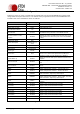
Table 9.1 Default Internal EEPROM Configuration .................................................... 23
List of Figures
Figure 1.1 – UM232R USB Serial UART Development Module ...................................... 1
Figure 4.1 Module Pin Out and Jumper Locations ....................................................... 7
Figure 5.1 UM232R Module Dimensions .................................................................... 11
Figure 7.1 Bus Powered Configuration ..................................................................... 16
Figure 7.2 Self-Powered Configuration ..................................................................... 17
Figure 7.3 Bus Powered with Power Switching Configuration .................................. 19
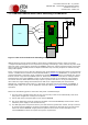
Figure 7.4 USB Bus Powered 3.3V Logic Drive .......................................................... 21
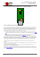
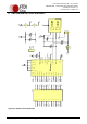
Figure 8.1 Module Circuit Schematic ......................................................................... 22