
Datasheet


© Copyright 2005-2011 Future Technology Devices International Ltd
23
Document Reference No.: FT_000051
UM232R USB - Serial UART Development Module
Datasheet Version 1.1
Clearance No.: FTDI# 125
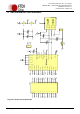
9 Internal EEPROM Configuration
Following a power-on reset or a USB reset the FT232R will scan its internal EEPROM and read the USB
configuration descriptors stored there. The default values programmed into the internal EEPROM in the
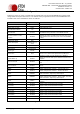
FT232RL used on the UM232R are shown in Table 8.1.
Parameter
Value
Notes
USB Vendor ID (VID)
0403h
FTDI default VID (hex)
USB Product UD (PID)
6001h
FTDI default PID (hex)
Serial Number Enabled?
Yes
Serial Number
See Note
A unique serial number is generated and programmed into
the EEPROM during final test of the UM232R module.
Pull down I/O Pins in USB
Suspend
Disabled
Enabling this option will make the device pull down on the
UART interface lines when the power is shut off (PWREN#
is high).
Manufacturer Name
FTDI
Product Description
UM232R USB <->
Serial
Max Bus Power Current
100mA
Power Source
Bus Powered
Device Type
FT232R
USB Version
0200
Returns USB 2.0 device description to the host. Note: The
device is be a USB 2.0 Full Speed device (12Mb/s) as
opposed to a USB 2.0 High Speed device (480Mb/s).
Remote Wake Up
Enabled
Taking RI# low will wake up the USB host controller from
suspend.
High Current I/Os
Disabled
Enables the high drive level on the UART and CBUS I/O
pins.
Load VCP Driver
Enabled
Makes the device load the CVP driver interface for the
device.
CBUS0
TXLED#
Default configuration of CBUS0 – Transmit LED drive.
CBUS1
RXLED#
Default configuration of CBUS1 – Receive LED drive.
CBUS2
PWREN#
Default configuration of CBUS2 – Power enable. Low after
USB enumeration, high during USB suspend.
CBUS3
PWREN#
Default configuration of CBUS3 – Power enable. Low after
USB enumeration, high during USB suspend.
CBUS4
SLEEP#
Default configurations of CBUS4 – Low during USB
suspend.
Invert TXD
Disabled
Signal on this pin becomes TXD# if enable.
Invert RXD
Disabled
Signal on this pin becomes RXD# if enable.
Invert RTS#
Disabled
Signal on this pin becomes RTS if enable.
Invert CTS#
Disabled
Signal on this pin becomes CTS if enable.
Invert DTR#
Disabled
Signal on this pin becomes DTR if enable.
Invert DSR#
Disabled
Signal on this pin becomes DSR if enable.
Invert DCD#
Disabled
Signal on this pin becomes DCD if enable.
Invert RI#
Disabled
Signal on this pin becomes RI if enable.
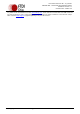
Table 9.1 Default Internal EEPROM Configuration