
Datasheet


© Copyright 2005-2011 Future Technology Devices International Ltd
19
Document Reference No.: FT_000051
UM232R USB - Serial UART Development Module
Datasheet Version 1.1
Clearance No.: FTDI# 125
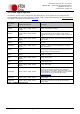
7.3 USB Bus Powered with Power Switching Confiduration
J2
2 1
1 2 3
J1
UM232R © FTDI 2008
FT232RL
FTDI
1
12 13
24
MCU
TXD
RXD
RTS#
CTS#
TXD
RTS# 3
RXD 5
GND 7
CTS# 10
18 CB3
14 USB
s d
g
P-Channel Power
MOSFET
1K
0.1uF 0.1uF
Soft
Start
Circuit
(PWREN#)
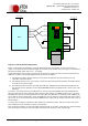
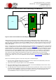
Figure 7.3 Bus Powered with Power Switching Configuration
USB Bus Powered circuits need to be able to power down in USB suspend mode in order to meet the
<=500μA total USB suspend current requirement (including external logic). Some external can power itself
down into a low current state by monitoring the PWREN# signal. For external logic that cannot power itself
down in this way the FT232R provides a simple but effective way of turning off power to external circuitry
during USB suspend.
Figure 7.3 shows how to use a discrete P-Channel Logic Level MOSFET to control the power to external logic
circuits. A suitable device would be an International Rectifier (www.irf.com) IRLML6402, or equivalent. It is
recommended that a “soft start” circuit consisting of a 1kΩseries resistor and a 0.1μF capacitor are used to
limit the current surge when the MOSFET turns on. Without the soft start circuit there is a danger that the
transient power surge of the MOSFET turning on will reset the FT232R, or the USB host / hub controller.
The values used here allow attached circuitry to power up with a slew rate of ~12.5V per millisecond, in
other words the output voltage will transition from GND to 5V in approximately 400 microseconds.
Alternatively, a dedicated power switch I.C. with inbuilt “soft-start” can be used instead of a MOSFET. A
suitable power switch I.C. for such an application would be a Micrel (www.micrel.com) MIC2025-2BM or
equivalent.
Please note the following points in connection with power controlled designs:
i) The logic to be controlled must have its own reset circuitry so that it will automatically reset itself
when power is applied on coming out of suspend.
ii) Set the Pull-down on Suspend option in the internal EEPROM.
iii) One of the CBUS Pins should be configured as PWE# in the internal EEPROM, and should be used to
switch the power supply to the external circuitry.
iv) For USB high-power bus powered device (one that consumes greater than 100mA, and up to 500mA
of current from the USB bus), the power consumption of the device should be set in the max power
field in the internal EEPROM. A high-power bus powered device must use this descriptor in the
internal EEPROM to inform the system of its power requirements.