
Datasheet


© Copyright 2005-2011 Future Technology Devices International Ltd
16
Document Reference No.: FT_000051
UM232R USB - Serial UART Development Module
Datasheet Version 1.1
Clearance No.: FTDI# 125
7 Module Configurations
7.1 BUS Powered Configuration
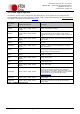
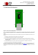
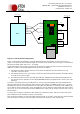
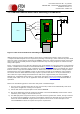
Figure 7.1 Bus Powered Configuration
Figure 7.1 illustrates the UM232R module in a typical USB bus powered design configuration. This can easily
be done by fitting the jumper link on J2, as shown above. The UM232R is supplied in this configuration by
default.
A USB Bus Powered device gets its power from the USB bus. Basic rules for USB Bus Power devices are as
follows:
i) On plug-in to USB, the device must draw no more than 100mA.
ii) On USB suspend the device must draw no more than 500μA.
iii) A Bus Powered High Power USB Device (one that draws more than 100mA) should use one of the
CBUS pins configured as PWREN# and use it to keep the current below 100mA on plug-in and 500μA
on USB suspend.
iv) A device that consumes more than 100mA cannot be plugged into a USB Bus Powered Hub.
v) No device can draw more that 500mA from the USB Bus.
Interfacing the UM232R module to a microcontroller (MCU), or other logic for a bus powered design would
be done in exactly the same way as for a self powered design (see Section 7.2), except that the MCU or
external logic would take its power supply from the USB bus (either the 5V on the USB pin, or 3.3V on the
3V3 pin).