
iCommand-Touch Manual


CAP-837
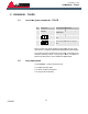
"Air circuit" and "Oil circuit"
screen
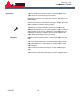
Fig. 8: "Air circuit" screen
Tap the
circuit and oil circuit are displayed schematically.
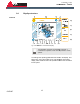
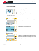
Fig. 9: "Oil circuit" screen
Tap the button to the
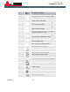
"Graphics" screen
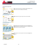
Fig. 10: "Graphics" screen
The "Graphics" button initially leads to an overview of all existing
graphical evaluation. The pressure, temperature, air quantity, usage
and maintenance intervals are displayed.
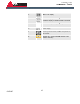
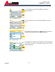
Fig. 11: "Pressure" screen
In the "Pressure" screen the pressure of the system is graphically
displayed.
iCommand
18
Tap the
"State"
button and the compressor stage is shown. The air
circuit and oil circuit are displayed schematically.
Tap the button to the
"right"
to get to the "Oil circuit" screen.
The "Graphics" button initially leads to an overview of all existing
graphical evaluation. The pressure, temperature, air quantity, usage
and maintenance intervals are displayed.
In the "Pressure" screen the pressure of the system is graphically
displayed.
iCommand – Touch
iCommand
- Touch
button and the compressor stage is shown. The air
to get to the "Oil circuit" screen.
The "Graphics" button initially leads to an overview of all existing
graphical evaluation. The pressure, temperature, air quantity, usage
In the "Pressure" screen the pressure of the system is graphically