
Product Manual


MASTERLINE SERIES CAP200
Page 17 of 46 REV H JUNE 2017
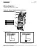
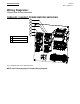
Wiring Diagrams:
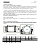
Simplex Single Phase and 3 Phase
TURN OFF / TAGOUT POWER BEFORE SERVICING
3
2
1
5
4
Fig. (10) Simplex Starter
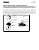
95 96
OL
Pressure
Switch
Power Supply
to L1 and L2
MS1
Motor
Jumper T2 to L3
M
L2
L3
L1
OL
A2A1
T3
T2
T1
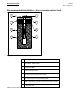
95 96
OL
Pressure
Switch
Power Supply to
L1, L2, and L3
MS1
Motor
M
L2
L3
L1
OL
A2A1
T3
T2
T1
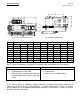
Fig (11) Single Phase wiring diagram Fig (12) Three phase wiring diagram
NOTE: The above wiring diagrams are valid for standard models only. Contact your local distributor for wiring
diagrams for factory installed options
1
L1
2
L2
3
L3
4
Overload relay
5
Reset switch