
Manual

2-5
2.4 Pre-Connection Preparations (cont.)
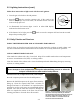
4. For rethermalizers equipped with casters, there are no built-in leveling devices. The floor where
the rethermalizer is to be installed must be level.
WARNING
Inlet water pressure must not exceed 80 PSI. A regulator must be installed between
rethermalizer water inlet and water supply when pressure exceeds 80 PSI.
5. Connect the water hose to the fitting at the rear of the unit. If inlet water pressure exceeds 80
PSI, a regulator must be installed to prevent damage to rethermalizer. Ensure that water
pressure to rethermalizer is less than 80 PSI.
NOTE 1: The unit may be equipped with an optional hose assembly with a quick-disconnect
coupling or hose provided by others. Whichever is used, it should be attached to a COLD
WATER SERVICE ONLY. Teflon thread-seal tape or Loctite PST56765 or equivalent
thread sealer must be used when installing the fittings.
4. Connect the desired drain plumbing to the 1¼" drain valve.
5. Test the equipment’s electrical system by plugging the power cord into a grounded 120VAC
outlet and pressing the computer’s ON/OFF button. °- or should appear in the
display.
6. Turn the computer off. Verify that the display is blank.
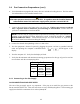
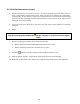
7. Verify that the minimum and maximum incoming gas pressures for the type of gas to be used are
in accordance with the accompanying table.
Incoming Gas Pressures
Gas Minimum Maximum
Natural
6" W.C.
1.49 kPa
14.93 mbar
14" W.C.
3.48 kPa
34.84 mbar
LP
11" W.C.
2.74 kPa
27.37 mbar
14" W.C.
3.48 kPa
34.84 mbar
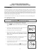
2.4.1 Connecting to the Gas Supply
GAS CONNECTIONS AND PIPE SIZES
The size of the gas supply pipe is very important. If the pipe is too small, the gas pressure at the
burner manifold will be low. This will cause slow recovery and delayed ignition. The incoming gas
supply line should be a minimum of 1½ inches (38mm) ID.