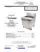
OPERATOR’S MANUAL FRYMASTER BIPH55/MPH55 SERIES GAS FRYER This equipment chapter is to be installed in the Fryer Section of the Equipment Manual. FOR YOUR SAFETY Do Not Store or use gasoline or other flammable vapors and liquids in the vicinity of this or any other appliance. MANUFACTURED BY P.O. BOX 51000 SHREVEPORT, LOUISIANA 71135-1000 PHONE: 1-318-865-1711 TOLL FREE: 1-800-551-8633 1-800-24 FRYER FAX: 1-318-219-7135 TABLE OF CONTENTS WARRANTY STATEMENT ...............................................
NOTICE IF, DURING THE WARRANTY PERIOD, THE CUSTOMER USES A PART FOR THIS ENODIS EQUIPMENT OTHER THAN AN UNMODIFIED NEW OR RECYCLED PART PURCHASED DIRECTLY FROM FRYMASTER DEAN, OR ANY OF ITS AUTHORIZED SERVICE CENTERS, AND/OR THE PART BEING USED IS MODIFIED FROM ITS ORIGINAL CONFIGURATION, THIS WARRANTY WILL BE VOID.
DANGER No structural material on the fryer should be altered or removed to accommodate placement of the fryer under a hood. Questions? Call the Frymaster Dean Service Hotline at 1-800-551-8633. DANGER Adequate means must be provided to limit the movement of this appliance without depending upon the gas line connection. All fryers equipped with casters must be stabilized by installing restraining chains.
WARRANTY STATEMENT Frymaster, L.L.C. makes the following limited warranties to the original purchaser only for this equipment and replacement parts: A. WARRANTY PROVISIONS - FRYERS 1. Frymaster L.L.C. warrants all components against defects in material and workmanship for a period of one year. 2. All parts, with the exception of the frypot, heating elements and fuses, are warranted for one year after installation date of fryer. 3.
D. WARRANTY PROVISIONS - COOKING COMPUTER 1. Frymaster L.L.C. warrants the M-2000 Cooking Computer against defective material or workmanship for a period of three years from the original installation date. If the unit fails within the first year, warranty will cover part and labor. If the part fails the second year, warranty will cover part only. Labor is charged to the store. The third year, warranty will cover the part at a reduced cost of $90.00. No labor or handling will be covered. 2.
BIPH55 / MPH55 SERIES GAS FRYER CHAPTER 1: INTRODUCTION 1.1 General Read the instructions in this manual thoroughly before attempting to operate this equipment. This manual covers all configurations of models MPH55 and BIPH55 fryers. Models designated MPH55 do not have built-in filtration systems. Models designated BIPH55 are equipped with FootPrint Pro built-in filtration systems.
1.2 Safety Information Before attempting to operate your unit, read the instructions in this manual thoroughly. Throughout this manual, you will find notations enclosed in double-bordered boxes similar to the ones that follow. CAUTION CAUTION boxes contain information about actions or conditions that may cause or result in a malfunction of your system.
The user may find the following booklet prepared by the Federal Communications Commission helpful: "How to Identify and Resolve Radio-TV Interference Problems". This booklet is available from the U.S. Government Printing Office, Washington, DC 20402, Stock No. 004-000-00345-4. 1.4 European Community (CE) Specific Information The European Community (CE) has established certain specific standards regarding equipment of this type.
1.7 Shipping Damage Claim Procedure Your Frymaster equipment was carefully inspected and packed before leaving the factory. The transportation company assumes full responsibility for safe delivery upon its acceptance of the equipment for transport. What to do if your equipment arrives damaged: 1. File a claim for damages immediately, regardless of the extent of damages. 2.
Service information may be obtained by contacting your local FASC/Distributor. Service may also be obtained by calling the Frymaster Service Department at 1-800-551-8633 or 1-318-865-1711.
BIPH55 / MPH55 SERIES GAS FRYER CHAPTER 2: INSTALLATION INSTRUCTIONS 2.1 General Installation Requirements Qualified, licensed, and/or authorized installation or service personnel, as defined in Section 1.6 of this manual, should perform all installation and service on Frymaster equipment. Conversion of this appliance from one type of gas to another should only be performed by qualified, licensed, and/or authorized installation or service personnel as defined in Section 1.6 of this manual.
DANGER No structural material on the fryer should be altered or removed to accommodate placement of the fryer under a hood. Questions? Call the Frymaster Dean Service Hotline at 1-800-551-8633. One of the most important considerations of efficient fryer operation is ventilation. Make sure the fryer is installed so that products of combustion are removed efficiently, and that the kitchen ventilation system does not produce drafts that interfere with burner operation.
DANGER This appliance is equipped with a special (grounding) plug for your protection against electrical shock, and must be plugged directly into a properly grounded receptacle. Do not cut, remove, or otherwise bypass the grounding prong on this plug! DANGER This appliance requires electrical power for operation. Place the gas control valve in the OFF position in case of a prolonged power outage. Do not attempt to operate this appliance during a power outage.
DANGER The appliance area must be kept free and clear of combustible material at all times. 3. Frymaster recommends that the minimum distance from the flue outlet to the bottom edge of the hood be 24 in. (600 mm) when the appliance consumes more than 120,000 BTU per hour. NOTE: There are no built-in leveling devices on fryers equipped with casters. The floor where the fryer is to be installed must be level. 4. Test the fryer electrical system: a.
Non-CE Standard for Incoming Gas Pressures Gas Natural LP Minimum 6" W.C. 1.49 kPa 14.93 mbar Maximum 14" W.C. 3.48 kPa 34.84 mbar 11" W.C. 2.74 kPa 27.37 mbar 14" W.C. 3.48 kPa 34.84 mbar 7. For fryers equipped with a FootPrint Pro system (BIPH55 models) plug the electrical cord(s) into a power receptacle behind the fryer. 2.4 Connection to Gas Line DANGER Before connecting new pipe to this appliance, the pipe must be blown out thoroughly to remove all foreign material.
Gas Connection Pipe Sizes (Minimum incoming pipe size should be 1 1/2" (41 mm)) Gas Natural Single Unit 3/4" (22 mm) Propane 1/2" (15 mm) Manufactured • 1" (28 mm) 2 - 3 Units 1" (28 mm) 4 or more units* 1 1/4" (36 mm) 3/4" (22 mm) 1" (28 mm) 1 1/4" (36 mm) 1 1/2" (41 mm) For distances of more than 20 feet (6 m) and/or more than 4 fittings or elbows, increase the connection by one pipe size.
CE Standard Required airflow for the combustion air supply is 2m3/h per kW. 1. Connect the quick-disconnect hose to the fryer quick-disconnect fitting under the front of the fryer and to the building gas line. NOTE: Some fryers are configured for a rigid connection to the gas supply line. These units are connected to the gas supply line at the rear of the unit. When using thread compound, use very small amounts on male threads only.
Non-CE Sta nda rd Burne r Ma nifold Ga s Pre ssure s Gas Pr e s s ur e 3" W.C. 0.73 kPa 8.25" W.C. 2.5 kPa Natural Propane 5. Check the programmed temperature thermostat setting. (Refer to the separate M2000 Manual furnished with your unit for the setpoint programming instructions for your particular controller.) 2.5 Converting to Another Gas Type DANGER This appliance was configured at the factory for a specific type of gas.
CE GAS CONVERSION INSTRUCTIONS 1. Between G20- and G25-type natural gas, adjust the gas pressure at the regulator. (Refer to the CE Standard Burner Manifold Gas Pressure Chart.) Do not change the orifice. 2. Between a 2nd family (G20 or G25) and a 3rd family gas (G30 butane or G31 propane): a. Change the orifices. b. Adjust the manifold pressure. 3. Affix the new label include with the conversion kit next to the existing rating plate stating that the gas type has been converted.
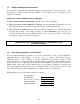
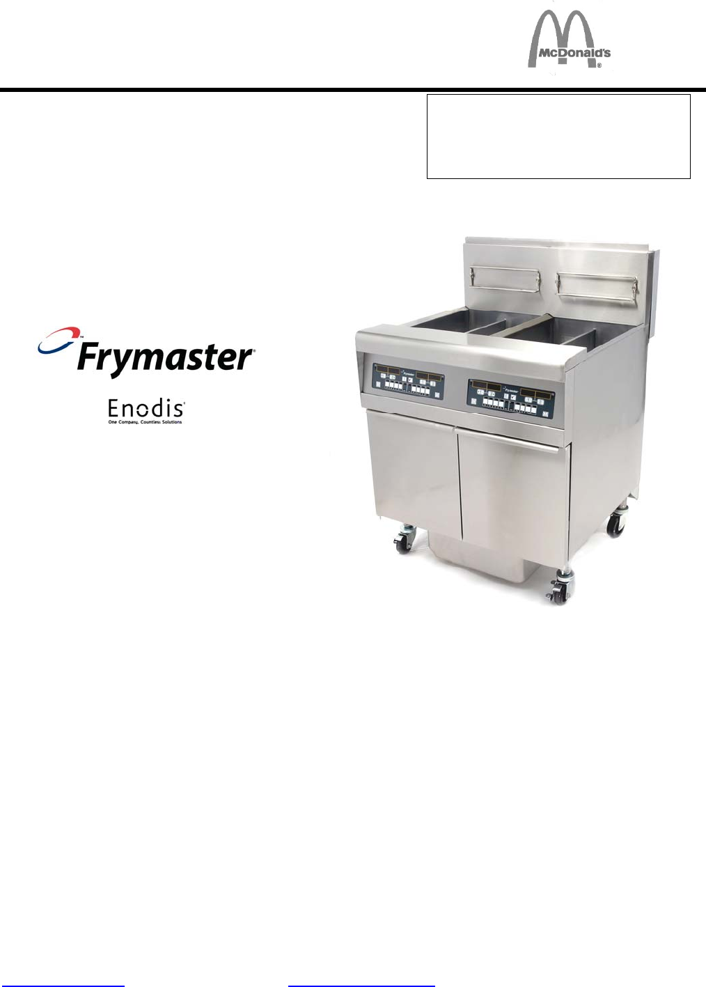
BIPH55 / MPH55 SERIES GAS FRYER CHAPTER 3: OPERATING INSTRUCTIONS FINDING YOUR WAY AROUND THE BIPH55 SERIES GAS FRYER Flue Cap Basket Hangers Flue Control Panel (M2000 Computer Shown) Top Cap Gas Valve Gas Valve Combustion Blower Filter Control Handles Drain Handles Combustion Blower FootPrint Pro Built-in Filtration Unit TYPICAL CONFIGURATION (BIPH255 SHOWN) NOTE: The appearance of your fryer may differ slightly from that shown depending upon configuration and date of manufacture.
3.1 Equipment Setup and Shutdown Procedures WARNING The on-site supervisor is responsible for ensuring that operators are made aware of the inherent hazards of operating a hot oil filtering system, particularly the aspects of oil filtration, draining and cleaning procedures. CAUTION If this is the first time the fryer is being used after installation, refer to the frypot BoilOut Procedure in Section 5.3.2.1 of this manual. CAUTION The oil/shortening capacity of the Pro Series gas fryer is 50 lbs.
3.1.2 Lighting the Fryer 1. Press the computer ON/OFF switch to the OFF position. After placing the ON/OFF switch in the OFF position, turn the gas valve knob to the OFF position. Wait 5 minutes, then turn the knob to the ON postion and proceed with Step 2. OFF ON OFF ON Placing the ON/OFF switch in the OFF position also turns off the gas valve. Wait five minutes before continuing with Step 2, which will also turn on the gas valve. Honeywell For Non-CE Fryers Honeywell For CE Fryers 2.
3.1.3 Shutdown For short-term shut down during the workday: 1. Place the computer ON/OFF switch in the OFF position and put the frypot covers in place. When shutting the fryers down at closing time: 1. Place the computer ON/OFF switch in the OFF position to turn the fryer off. OFF OFF ON After placing the ON/OFF switch in the OFF position, turn the gas valve knob to the OFF position. Honeywell Placing the ON/OFF switch in the OFF position also turns off the gas valve.
BIPH55 / MPH55 SERIES GAS FRYER CHAPTER 4: FILTRATION INSTRUCTIONS 4.1 Introduction The FootPrint Pro filtration system allows the oil in one frypot to be safely and efficiently filtered while the other frypots in a battery remain in operation. Section 4.3 covers preparation of the filter system for use. Operation of the system is covered in section 4.4.
2. Position a metal container with a sealable cover under the drainpipe. The metal container must be able to withstand the heat of the oil and hold hot liquids. 3. Open the drain valve slowly to avoid splattering. If the drain valve becomes clogged with food particles, use the Fryer’s Friend (poker-like tool) to clear the blockage. DANGER NEVER attempt to clear a clogged drain valve from the front of the valve! Hot oil or shortening will rush out creating the potential for severe burns.
2. Inspect the filter pan connection fitting to ensure that both O-rings are in good condition. (See Figure 2) Inspect the filter connection fitting O-rings. Figure 2 3. Then in reverse order, place the metal filter screen in the center of the bottom of the pan, then lay a filter pad over the screen, ensuring that the textured side of the pad is up. Make sure that the pad is in between the embossed ridges of the filter pan then position the hold down ring on top of the pad.
DANGER NEVER attempt to clear a clogged drain valve from the front of the valve! Hot oil will rush out creating the potential for severe burns. DO NOT hammer on the drain valve with the cleanout rod or other objects. Damage to the ball inside will result in leaks and will void the Frymaster warranty. 2. After the oil has drained from the frypot, rotate the filter handle to start the pump and begin the filtering process. There may be a slight delay before the pump activates.
DANGER The crumb tray in fryers equipped with a filter system must be emptied into a fireproof container at the end of frying operations each day. Some food particles can spontaneously combust if left soaking in certain shortening material. WARNING Do not bang fry baskets or other utensils on the fryer’s joiner strip. The strip is present to seal the joint between the fry vessels. Banging fry baskets on the strip to dislodge shortening will distort the strip, adversely affecting its fit.
BIPH55 / MPH55 SERIES GAS FRYER CHAPTER 5: PREVENTIVE MAINTENANCE 5.1 Fryer Preventive Maintenance Checks and Service DANGER The crumb tray in fryers equipped with a filter system must be emptied into a fireproof container at the end of frying operations each day. Some food particles can spontaneously combust if left soaking in certain shortening material. WARNING Use McDonald’s All Purpose Concentrate. Read the directions for use and precautionary statements before use.
WARNING Never use the filter pan to transport old oil to the disposal area. WARNING Never drain water into the filter pan. Water will damage the filter pump. There are no periodic preventive maintenance checks and services required for your FootPrint Pro Filtration System other than daily cleaning of the filter pan with a solution of hot water and McDonald’s All Purpose Concentrate.
DANGER Ensure that the frypot is completely free of water before filling with oil or shortening. When the oil or shortening is heated to cooking temperature, water in the frypot will cause splattering. 5.3.3 Clean Filter Pan, Detachable Parts and Accessories As with the frypot, a deposit of carbonized oil or shortening will accumulate on the filter pan and detachable parts and accessories such as baskets, sediment trays, or fishplates.
Wiring connection Blower assembly mounting nuts Figure 1 2. Remove the three fasteners that secure the blower motor assembly to the blower housing, and separate the two components. (See Figure 2) Remove these fasteners. Figure 2 3. Wrap the motor with plastic wrap to prevent water from entering it. Spray degreaser or detergent on the blower wheel and the blower housing. Allow it to soak for five minutes. Rinse the wheel and housing with hot tap water, then dry with a clean cloth.
4. Remove the plastic wrap from the blower motor assembly. Reassemble the blower motor assembly and blower housing. Reinstall the blower assembly in the fryer. 5. Reinstall the blower shield or shield assembly. 6. Light the fryer in accordance with the procedure described in Chapter 3, Section 3.1. 7. After the burners have been lit for at least 90 seconds, observe the flames through the burner viewing ports located on each side of the combustion air blower.
5.6 SEMI-ANNUAL CHECKS AND SERVICE 5.6.1 Clean Gas Valve Vent Tube NOTE: This procedure is not required for fryers configured for export to CE countries. 1. Set the fryer power switch and the gas valve to the OFF position. 2. Carefully unscrew the vent tube from the gas valve. NOTE: The vent tube may be straightened for ease in removal. 3. Pass a piece of ordinary binding wire (.052 inch diameter) through the tube to remove any obstruction. 4.
• Verify that component box components (i.e. computer, transformers, relays, interface boards, etc.) are in good condition and free from oil and other debris. Inspect the component box wiring and verify that connections are tight and that wiring is in good condition. • Verify that all safety features (i.e. drain safety switches, reset switches, etc.) are present and functioning properly.
BIPH55 / MPH55 SERIES GAS FRYER CHAPTER 6: OPERATOR TROUBLESHOOTING 6.1 Introduction This chapter provides an easy reference guide to some of the common problems that may occur during the operation of your equipment. The troubleshooting guides that follow are intended to help you correct, or at least accurately diagnose, problems with your equipment. Although the chapter covers the most common problems reported, you may encounter problems that are not covered.
6.2 Troubleshooting Fryers 6.2.1 Computer and Heating Problems PROBLEM PROBABLE CAUSES A. No power to fryer. B. Damaged computer wiring harness. C. Failed Computer No display on the computer. D. A. B. C. Fryer does not heat. D. E. F. Fryer is operating normally, but recovery is slow when cooking. CORRECTIVE ACTION A. Verify that the fryer is plugged in and that the circuit breaker is not tripped. B. Call FASC. C. Call FASC. D.
PROBLEM PROBABLE CAUSES CORRECTIVE ACTION A. Dirty or obstructed combustion air A. Clean and adjust per instructions blower. in Chapter 5 of this manual. Fryer is operating normally, but produces a popping sound when burners B. Dirty or obstructed gas valve vent B. Clean per instructions in Chapter tube (non-CE fryers only). 5 of this manual. ignite. C. Malfunctioning combustion air blower. Computer will not go into program mode or some buttons do not actuate.
Problem M2000 display shows LOW TEMP. M2000 display shows PROBE FAILURE. M2000 display shows IGNITION FAILURE. M2000 display shows HI-LIMIT. Display shows , heating indicator cycles on and off normally, but burners will not light and blower is not running. Heat indicator off upon initial startup. Display shows , or with alarm sounding.
Problem M2000 display shows HI 2 BAD. 6.4 Probable Causes Computer in hi-limit test mode. Corrective Action This is displayed only during a test of the hi-limit circuit and indicates that the hi-limit has failed. DO NOT OPERATE THE FRYER! Call FASC. Troubleshooting the Built-in Filtration System PROBLEM Pump won’t start. OR Pump stops during filtering. PROBABLE CAUSES A. Thermal overload switch has tripped on an overheated motor.
PROBLEM Continued from Previous page Filter Pump starts, but no transfer takes place or the oil return is very slow. PROBABLE CAUSES C. Blockage in filter pump. CORRECTIVE ACTION C. Pump blockages are usually caused by sediment build-up in the pump due to improperly sized Test: Close the drain valve. Place the or installed filter pad and failure filter handle in the OFF position, to use the crumb screen.
6.6 Replacing the Controller or Controller Wiring Harness 1. Disconnect the fryer from the electrical power supply. 2. The controller bezel is held in place by tabs at the top and bottom. Slide the bezel up to disengage the lower tabs. Then slide the bezel down to disengage the upper tabs. 3. Remove the top two screws in the upper corners of the control panel. 4. Hinge the controller down. Allow it to rest on its hinge tabs to access the 15-pin connector on the Ignition Module back.
THIS PAGE INTENTIONALLY LEFT BLANK
Frymaster, L.L.C.