
User Manual

www.frsky-rc.com
28/03/2011
5 Specifications
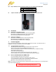
5.1 Receiver specifications
Model: D8R (V2)
Number of Channels: 8
Weight: 16.2g
Dimension: 54*27*17mm (2.13” x 1.06” x 0.67”)
Operating Voltage Range: 3.5V-10.0V
Operating Current: 100mA
Specified Range: 1.5km (Ground Range)
Resolution: 3072 (>11bit)
Switchable Frame Rate: 18ms (FS) for analog servos or 9ms (HS) for digital servos
Built-in battery voltage sensor: Sent on A1 analog channel to transmitter
Analog input voltage (A2): 0~3.3V from user supplied sensor
Upgradable firmware without opening the receiver case
Model: D6FR
Number of Channels: 6
Weight: 7.1g
Dimension: 42*22*11mm (1.65” x 0.87” x 0.43”)
Operating Voltage Range: 3.5V-10.0V
Operating Current: 50mA
Specified Range: 1.5km (Ground Range)
Resolution: 3072 (>11bit)
Switchable Frame Rate: 18ms (FS) for analog servos or 9ms (HS) for digital servos
Built-in battery voltage sensor: Sent on A1 analog channel to transmitter
5.2 Transmitter module specifications
Model: DFT, DJT, DHT
Operating Voltage Range: 6.0V-13.0V
Operating Current: 50mA
Output Power: 60mW
Resolution: 3072
6 How To Use
6.1 Setup
6.1.1 Installation of the transmitter modules:
6.1.1.1 Remove the original transmitting module.
6.1.1.2 Ascertain that the transmitter is set to broadcast PPM and not PCM. Turn off the transmitter.
6.1.1.3 Put the FrSky 2.4GHz transmitter module into the module port of your RC transmitter and screw on
the transmitting antenna. The DHT module may be internally installed in the transmitter.
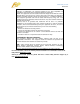
6.1.1.4 Check the MODE switch to its corresponding position.
Mode Switch 1 Switch 2 Mode
1 OFF OFF Two-way Mode
2 OFF ON V8 Mode
3 ON OFF Not Defined
4 ON ON Firmware Upgrade
Important!
The effective range of control refers to the distance between the transmitter and the receiver. All
data was tested and verified by FrSky. However this is not guaranteed due to many factors
such as the flying environment and the weather, which can greatly affect the effective range of
control.
It is extremely important to range check your models prior to each flying session!
6.1.1.5 Turn the transmitter power on and check the LED status on the module. Normal operation on the
transmitter is indicated with the RED LED on and the GREEN LED flashing.
6.1.2 Installation of receivers:
2