
User Manual
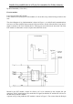
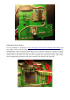

Finally the processor board.
This was modified as described in http://code.google.com/p/gruvin9x/wiki/FrskyInterfacing with
two, surface mount resistors being removed to allow the serial connections to be made to the
ATMEGA64A, and two currently unused pins wired via 220 ohm resistors to to replace the signals
disconnected by removing the resistors, see Figure 4. Not shown is resistor R2 on the circuit. This is
wired in-line on the white wire from the servo connector the the processor board. This resistor
allows programming operations to take place with the serial interface still connected.
Figure 3
Figure 4