
User Manual
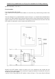

has sleeving over the bare wire to ensure it does not short to anything else. The wire from the Txd
pin is kynar, a single strand insulated wire. Stranded wire is not advisable as it is very easy to allow
a strand to short to an adjacent pin. At the four pin, external connector the wires are wrapped round
the pin close to the circuit board and then soldered. These pins a sufficiently long that a mating
connector will still fit when the wires have been soldered in place.
At the other end the wires are soldered to the pads by the pins. I did not use the hole, and made sure
there were no shorts to the holes. Using a fine tipped soldering iron these wires were soldered
without removing the board from the plastic case. Care needs to be taken not to melt the case with
the iron. It is a very small space due to the daughter board with the switches and LED sticking up.
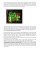
Now for the board in the back of the transmitter.
This board is shown in Figure 3. To use the two pins from the DJT module, they need to be isolated
from the board. Pin 5, labelled DJT Tx in the picture, only needed a single cut on the visible side of
the board, it may be seen just by the end of the orange wire. Pin 2, labelled DJT Rx in the picture,
needed one cut on the visible side, and two on the side towards the module. The board will, of
course, need to be unscrewed to get at the other side
I had a MAX232 board available so I used that, if you do not have a suitable board you could make
the circuit on a small piece of stripboard.
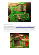
Power and ground for the board was obtained from the 12 way connector, the white wire is +5volts
and the grey wire is ground. It is always wise to check this with a meter before wiring up.
The pins from the module were wired to the board (purple and orange wires). The other side of the
MAX232 board were wired using a servo extension lead to provide a means of disconnecting the
front and back halves of the case (red and white wires).
The board was then glued to the back board with a small square of depron between them to provide
isolation so the pins of the MAX232 board could not rub on the back board. The servo connector
was also glued to the back board, and all the wires tack glued to prevent movement and strain on the
soldered joints.
Figure 2