
User Manual

Details of my modification to a Flysky 9x transmitter for FrSky telemetry.
By Mike Blandford (12 Jun 2011).
First the module.
I am using the FrSky DJT module.
I have used the two unused pins in the module so I do not have any external wiring or holes in the
case.
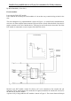
The circuit diagram of my implementation is shown in Figure 1. As with all serial communications,
care has to be taken with the names transmit (Txd) and receive (Rxd). Often the Rxd of one device
needs to connect to the Txd of another device. This may be seen on the circuit where the Txd of the
DJT module is connected to a receive input of the MAX232 device.
Internal to the DJT module, resistor R1 allows a PC to be connected to the external four pin
connector. The PC serial output will override the 9X signal, but both the PC and the 9X will receive
the data sent by the DJT module.
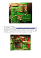
A picture of my wiring inside the DJT module is shown in Figure 2. The resistor from the Rxd pin
Figure 1