
User Manual

www.frsky-rc.com
18/05/12
2
indicating the failsafe position has been set in the receiver.
To disable the failsafe function, re-bind the receiver.
Failsafe is recommended to set when system is firstly used, or receiver has been re-bound. Follow steps below to set
failsafe.
Option-1. How to set failsafe to a user-determined state on lost signal:
1) Bind the receiver to the transmitter module first and turn on both the transmitter and the receiver;
2) Move the controls to desired failsafe position for all channels;
3) Press briefly the F/S button on the receiver and you are done.
Option-2. How to set failsafe for no pulses on lost signal:
1) Just press briefly the F/S button on the receiver while the transmitter is off and you are done.
Note: If failsafe is not set, failsafe default will hold last position before signal is lost. In this case, there exists risk that
your model will fly away or cause injury.
2.4 LED status
RED LED GREEN LED Mode
Off Dimly On Normal Operation
Blinking Off No Signal
Blinking On Binding Successful
2.5 Pins definition for side ports
It should be noted that 3.3V only has a limited driving current (1~10mA), it should not be used for driving a MPU.
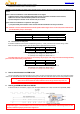
2.5.1 Two external analog telemetry ports (A1&A2) and one digital data-stream port (Rx).
G G G
Tx X X
Rx A2 A1
Rx: input to receiver, RS232 level, connect with FrSky sensor hub
A2 (external): max voltage 3.3V, division ratio 1:1
A1 (external): max voltage 3.3V, division ratio 1:1
2.5.2 When side port pins of A1 and X are connected by the jumper, A1 will change from external analog telemetry
port to internal built-in battery voltage sensor.
G G G
Tx X X
Rx A2 A1
Rx: input to receiver, RS232 level, connect with FrSky sensor hub
A2 (external): max voltage 3.3V, division ratio 1:1
A1 (internal): max voltage 3.3V, division ratio 4:1
3. How to switch between two PPM modes
Turn the transmitter off, connect the battery to the receiver, pressing the F/S button of the receiver for 6 seconds and then
release. The red LED will flash fast in HS mode and slowly in FS mode. The mode alternates each time this procedure is done.
Warning: HS mode is only applied for high-speed digital servos.
Other servos should select FS mode, otherwise servos will get hot and may burn out.
4. How to get CPPM and RSSI from D8R-XP
If CH3 and CH4 are connected by a jumper, CH1 will output CPPM for CH1~CH8, and CH2 will output RSSI (PWM).
CPPM channel can not handle all eight channels at the same time with all throws are maxed out, as it does not have
enough frame gap. It is recommended to use at most six channels from CPPM channel while leaving off the rest two
channels, otherwise improper performance might occur.