
User Manual


BlankingtheOSDdisplay
Thepadsmarked‘PWM’maybeusedtoblanktheOSDdisplayduringflight.Twoconnection
possibilitiesexist:
1) Takea3‐pin0.1”header,trimthepinsalittle,and solderthemintothethreeholes.
2) Takeastandard3‐wireservocable,andsolderthethreewiresto
thethreePWMpads.
Inbothcases,theleft‐mostPWMpinisthePWMsignal(orange,white,oryellowintheservocable),
andtheright‐mostisground(blackorbrownintheservocable).
NotethatwhentheOSDdisplayisblanked,anyalarmwillcausethe
displaytoreturn.Agoodexample
ofthisisalow‐voltagealarm,thiswillun‐blankthedisplay,andwarnthepilottolandquickly.
RxRSSIDisplay
Thepinsmarked‘ANA’areananaloginput,whichmaybeusedtoshowthereceiversignalstrength.
NotethatEzOSDFirmwarerev.0.99orlaterisrequiredtotakeadvantag eofthisfeature.
InordertousetheRSSIfeatureyou’llfirstneedtofindtheRSSIvoltageoutputpin
insideyourRC
receiver,whichmeansopeningupyourRCreceiver.Takenotionthatdoingsowillvoiditswarranty,so
don’tattemptthisunlessyou’reconfidentyouwillbeabletosuccessfullyputit backtogetheragain.
Mostmodernreceiversusesurfacemounttechnologywhichgetssmallerwitheach
revision.Thismakes
solderingontotheRSSIpinverydifficultandreallynotrecommendedunlessyouarequiteskilledinthe
artofsoldering.Obviouslywetakenoresponsibilityifyouturnyourpreciousreceiverintoamolten
blobofsolderandplastic,somakesureyou’vegottherighttools
andexpertisetocompletethis
modificationsuccessfully.
MostreceiversusethesamechipsetfortheRFfrontendandhenceuseasimilarRSSIimplementation.A
popularICusedintheRFfrontendofRCreceiversistheToshibaTA31136,thisiscommonlyusedbyRC
receiversfromFutabaforexample.
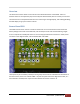
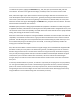
PicturedbelowistheFutabaR168DPPCMreceiverwithcircledinbluetheRSSIoutputpin.Simply
solderingapieceofwiretothispinandanearbygroundconnecti on(forexamplethegroundofthestrip
ofservooutputpins)androutingthesewirestothesensorboardoftheOSD
willbesufficient.However
careshouldbetakenthatthiswireiskeptasshortaspossibleandroutedclearof‘noisy’wires,suchas
thoseconnectedtothebattery,ESCandmotor.
ImmersionRC|EzOSDManual
4