
User Manual

1/3
Gabriel Staples
http://electricrcaircraftguy.blogspot.com/
(blog includes articles such as “Parallel Charging LiPo Batteries,” “Beginner RC
Airplane Setup,” and “Buying Parts for the FliteTest Nutball Swappable.”)
6 Sept. 2013
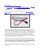
On the next page is the schematic from my engineering book of the FrSky Battery Voltage
Sensor, as shown here:
http://www.hobbyking.com/hobbyking/store/uh_viewitem.asp?idproduct=16671&aff=281904
The voltage sensor is simply a voltage divider, with a filter capacitor, in order to lower the
voltage from your LiPo battery to a safe level for the ADC (Analog to Digital Converter) in the
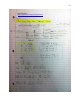
receiver. On the right side of my schematic below, the FrSky Battery Voltage sensor has 4
solder pads, with the bottom one being ground, and the other 3 being for different voltage divider
options. By soldering your positive wire to the correct pad, you maximize your voltage reading
resolution, while getting the right input range. The stock configuration has the red wire
connected to the top pad, which allows a maximum input voltage of 19.8V. Any higher than
that, and the output voltage (left side of the schematic) will exceed 3.3V, which is the maximum
safe input voltage for the ADC on the FrSky receiver (Rx).
If you’d like to make your own voltage divider, using resistors on-hand, instead of purchasing
this unit, all you need is R
1
and R
2
in the schematic. The filter capacitor (ceramic) is optional,
but will improve the smoothness of the voltage output to the Rx. To make a voltage divider for
a 3S LiPo, for instance, using resistors on-hand, choose R
1
and R
2
such that R
1
/(R
1
+ R
2
) =
1/6, and so that the sum of R
1
+ R
2
is somewhere between 1.5kΩ ~ 30kΩ*.
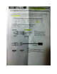
*Notes: 1) the absolute minimum sum of R
1
+ R
2
that you can use in this example is 1.307kΩ,
for ¼ Watt resistors. 2) Also, the FrSky Battery Voltage Sensor uses a sum of R
1
+ R
2
= 1.5kΩ +
7.5kΩ = 9kΩ.