
User Manual


3.2.1 D8R-II receiver (additional information)
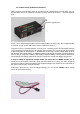
D8R-II receiver has 2 telemetry ports A1 and A2 (you can simultaneously connect either only 2 of
any telemetry sensors or more than 2 sensors by using special sensor-hub) + 1 firmware upgrade
port.
A1
A2
Firmware upgrade port
Port A1 has a default bridge installed from the factory between Х and A1 pins. Pin Х supplies power
to a sensor. А1 pin receiver data from a sensor. G stands for Ground.
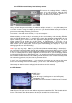
Therefore, if there is a bridge between X and A1 pins – telemetry screen FLD-02 would show the
inner RX voltage in the left cell “A1 & A2 Voltage” (look at section 3.3.1 of this manual) The readings
of this cell A1 (left) on “DATA Screen 1” would be true (4.2V) only in case if voltage divider for A1 is
set correctly. Don’t forget that this is stabilized voltage inside the RX circuit that is supplied either by
ESC (in case of using only 1 battery in RC-model) or separate battery used to power-up electronics.
Consequently, this reading could not be used as a reference to overall main battery charge level.
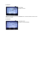
In order to setup an appropriate voltage divider you should turn to “MENU” Screen (look at
section 3.2 of this manual) “Volt Ratio” value (left value stands for А1 port)). This value should be
equal to the number of cells of the battery, that supplies voltage to the receiver (3 for 3-cells LiPO). If
this value is set correctly – it would read 4.2V
Furthermore, apart from A1 inner RX voltage readings, you can connect FBVS01 battery voltage
sensor to A2 RX telemetry port.