
User Manual

2
c. Press briefly the button on the Decoder and select the servo connection port
number that you want to set channel (see LED number and PWM servo
connection port number for details).
d. Set the channel select switch to the channel number you require.
e. Hold down the set switch for approx. 1second. The RED LED blinks rapidly at
approx. 5times/second, and it lights steadily, indicating the channel setting
procedure is completed.
f. To set channels for other servo connection ports, repeat from step c to e.
* Channel Setting with FrSky TFR8SB receiver:
a. Connect the SB port and RSSI port by the provided cable with TFR8SB.
b. Connect the battery to any of the 8 servo output channels.
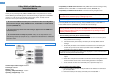
c. Connect the SBUS connector of FrSky Decoder to any of the available servo
output channels, and press briefly the button on the Decoder and select the
servo connection port number that you want to set channel (see LED number
and PWM servo connection port number for details).
d. Disconnect both the battery and the Decoder.
e. Connect the Decoder to the channel number you require (see chart below), and
then connect the battery to any of the available servo output channels. RED
blinking LED indicating the channel setting is completed in Mode A. To switch to
Mode B, press the button on receiver for three seconds until GREEN LED starts
to blink, indicating the channel setting is completed in Mode B.
Mode A: RED LED blinks
Mode B: GREEN LED blinks
f. To set channels for other servo connection ports, repeat from step c to e.
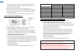
Channel Setting
Output Connector
Mode A Mode B
1 1 9
2 2 10
3 3 11
4 4 12
5 5 13
6 6 14
7 7 15
8 8 16
* Channel Setting with Futaba SBUS receivers (R6208SB etc.):
a. Connect the accessory short-plug to the DATA port of R6208 receiver.
b. Connect the battery to any of the 8 servo output channels.
c. Connect the SBUS connector of FrSky Decoder to any of the available servo
output channels, and press briefly the button on the Decoder and select the servo
connection port number that you want to set channel (see LED number and PWM
servo connection port number for details).
d. Disconnect both the battery and the Decoder.
e. Connect the Decoder to the channel number you require (see chart above), and
then connect the battery to any of the available servo output channels. At once
when turning on the receiver, the channel setting is completed in mode A. To
switch to mode B, press the Link/Mode button until the red and green LED starts
to blink simultaneously. The channel setting is completed in mode B.
Mode A: Red blinks 3 times
Mode B: Green blinks 3 times
f. To set channels for other servo connection ports, repeat from step c to e.
Note: After the channel settings are completed, recycle the power and check if
they are really under control of corresponding channels.
Note:
1. Follow the channel setting methods above for CPPM usage.
2. When the signal is lost, SBUS mode and CPPM mode will hold the last position.
Failsafe is recommended to set on the receiver side to make sure the servos
connected to the Decoder will be under control when the signal is lost.