
User Manual
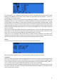
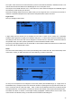

● The weight (in %) of the input can be set. This sets how much of the input control has to be mixed in. A
negative value inverts the response.
● An offset on the input value can be added.
● A trim can be used, for sticks this is by default the trim associated to the stick, but can be chosen to be
one of the other trims (for cross-trimming for example) or disabled altogether. For other inputs the trim
defaults to OFF, but can of course be set to one if required.
● Either a differential value can be set (reduces response by the specified percentage on one side of the
throw) or a curve (built-in or custom) can be assigned. When a custom curve is selected, a press of the
MENU key will bring you to the curve editor.
● The modes the mixer line is active in can be selected (see D/Rs).
● A switch (physical or virtual) can be used to activate the mixer line.
● A sound warning (1, 2 or 3 beeps) can be set to play whenever the line is active.
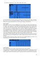
● The Multpx setting defines how the current mixer line interacts with the others on the same channel.
"Add" will simply add its output to them, "Multipl" will multiply the result of the lines above it, and
"Replace" will replace anything that was done before it with its output. The combination of these
operations allows creating complex mathematical operations.
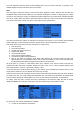
● Response of the output can be delayed and/or slowed down with regard to the input change. Slow could
for example be used to slow retracts that are actuated by a normal proportional servo. The time is how
many seconds the output will take to cover the -100 to +100% range.
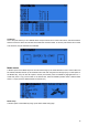
As a little example, if you wanted to add some compensation on the elevator channel when you increase
throttle, you would go through a simple path:
● What's the control surface I want this to act on? Elevator,
which
is
connected
to
CH2.
● When do I want it to move? When I move the throttle stick
, in addition to whatever would already be
present (usually the elevator stick).
So you would simply go on CH2, and insert a new line with Thr as source. Type would be Add as the
compensation needs to be added to the "normal" elevator response. As the required compensation is likely
small, you will dial in a small weight, maybe 5%. On the ground with motor disconnected, you will check the
elevator compensates in the correct direction. If not, you'll invert the weight to -5%.
You could then assign a switch, in order to be able to activate/deactivate it in flight to see if the amount of
compensation is actually appropriate. If the correction is more complicated, you might want to assign and create
a curve that matches what's required.
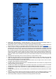
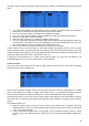
Servos
The SERVOS page is the interface between the setup "logic" and the real world with servos, linkages and
control surfaces. Up to now, we have set up what we want our different controls to do, now is the time to adapt
that to the mechanical characteristics of the model.
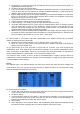
For each channel, we can define:
● A name, that will be shown on the mixer screen when the cursor is on a line belonging to that channel,
on the channel monitor and on the failsafe settings page.
● An offset or subtrim.
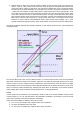
● Low and high limits. These are "hard" limits, i.e. they will never be overridden, so as long as they are set
so that your servo never forces, it really never will. They also serve as gain or "end point settings", so
reducing limit will reduce throw rather than induce clipping.
● Servo reverse.
● Center adjustment. This is similar to subtrim, with the difference that an adjustment done here will shift
the entire servo throw (including limits), and won't be visible on the channel monitor.
17