OpenTX for FrSky Taranis Manual by Andre Bernet, based on OpenTX r2940, last updated 14.04.27. Commercial use forbidden without explicit authorization of the authors and translators.
Sticks screen Model setup guidelines Advanced features Flight modes Telemetry values Audio Global variables A few interaction examples Introduction to OpenTX companion Basic concepts Setting up OpenTX companion for the Taranis Simulating the radio Flashing your Taranis radio Installing the driver (for Windows only) Installing the flashing utility (for Mac OS and Linux) Downloading and flashing the firmware What y
manufacturers place on their offerings, and as such offers features that match and even exceed those of the highest end radios in the industry. It is also future-proof, as both teams are always there to respond to questions and suggestions. Things can evolve quickly to follow the needs of the various users! And should you have some programming experience the entire source code of the firmware is available for you to play with and change to your liking.
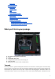
The hardware The radio has a relatively standard design and control layout, namely: ● ● ● ● ● ● 2 sticks and their associated trims, labelled in the software as Thr, Rud, Ele, Ail and TrmT, TrmR, TrmE, TrmA respectively. The stick to name mapping matches the selected stick mode. Trims are freely assignable (e.g. for cross-trimming), and can also be used as independent controls.
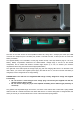
The back of the radio shows the JR-compatible module slot, along with a JR-style jack trainer port, USB connector and earphone jack. The battery bay houses a microSD card slot, a serial port and of course the battery connection. The supplied battery is a 6-cell NiMH, but the plug will also accept a JST-style balance plug for a 2s Li-Po battery. Battery compartment dimensions are 108x31x28mm. Voltage range is 5.
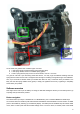
On the inside, the gimbals have 3 different types of screws: ● ● ● Y axis ratchet and/or "smooth braking" action strengths (blue) Y axis spring disable, screw it in to disable spring (green) X and Y spring tension (red), screw in for more tension, outer is Y of course.
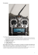
key goes to the next page, while a LONG press goes back to the previous one. EXIT goes back to the main views. In all model menu pages a long press of the MENU key will bring up a channel monitor to allow quickly checking the influence of a change in settings on the outputs. The navigation in a menu is simple: The +/- keys will navigate up/down between editable fields, or lines of fields depending on the screen. ENTER will enter the line of fields when applicable, then edit mode.
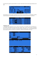
The third shows again the physical switches on the left, and the states of the 32 custom (logic) switches on the right. The last view is a channel monitor showing the servo outputs for all 32 channels (+/- change page). If channel names are defined on the SERVOS page, they will show up here instead of the numbers for convenience. Telemetry view A LONG press of the PAGE key from any of the main views brings up the telemetry views.
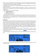
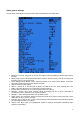
Radio general settings A LONG press of the MENU key brings up the mostly self-explanatory radio setup menu: ● ● ● ● ● ● ● ● ● ● ● Date/Time: To be set, they serve as info but also to give a correct timestamp to files and logs saved by the radio. Battery range: range of the graphical radio battery meter on the main views. To be set accordingly with the battery type you use (2s lipo here).
● ● ● ● ● Voice language: Allows you to choose the language of the voice announcements. Note that the list contains all supported languages, but you also need to ensure a voice pack for that language has been loaded onto the SD card (in a subfolder of the SOUNDS directory). Units: Allows choosing between metric and imperial units for telemetry values.
This page allows you to configure the trainer function for "master" use (make sure the Trainer mode in model settings is set to Master). For each of the 4 main functions you will be able to set the mode (OFF, += for Add, := for Replace), ratio and input channel. Start by setting the mode for each function (the "standard" way is Replace i.e.
Calibration This is the place where you can calibrate sticks and pots. Follow the on-screen instructions, and note that when asked to center the sticks this includes the throttle stick and the 2 sliders. S1 and S2 pots however do not need to be centered, only the extremes are calibrated. Model menus A SHORT press of the MENU key from the main views brings up the model selection screen.
● ● ● ● ● ● ● ● ● ● ● ● Model name: Self-explanatory... Change letter with +/- keys, go to the next with ENTER SHORT, or press ENTER LONG to capitalize the current letter before switching to the next. Model image: There you can select a 64x32px, 16-grayscale .bmp file located in the BMP folder of the SD card as your model logo. To be able to preview the images in the folder, use the S D Browser.
● Internal RF: ○ Mode: Transmission mode of the internal RF module (OFF, D16, D8, LR12). ○ Channel range: Choice of which of the radio's internal channels are actually transmitted over the air. ○ Receiver no (D16 / LR12 only): defines the behavior of the receiver lock function. This number is sent to the receiver, which will only respond to the number it was bound to. By default this is the number of the model's slot when it is created.
The inputs of this mixer are the Ail and Ele sticks, plus the virtual channel selected in "Collective source". This channel would see entries added on the MIXER page for one or more pitch curves. The outputs of the CCPM mixer are CYC1, CYC2 and CYC3, which need to be assigned on the MIXER page to the channels you will connect your servos to. Note that the settings made here have no effect unless you are using those CYC1, CYC2 and CYC3 sources.
The Side parameter limits the effect of that formatting line to only one side of the stick. A summary of the selected modes for each line is shown on the main screen. Mixer The next page is where the actions on the controls will be mapped to servos. OpenTX does not have any predefined mixing functions that relate only to a particular model type or situation, it rather gives you a blank canvas you can build upon.
● ● ● ● ● ● ● ● ● The weight (in %) of the input can be set. This sets how much of the input control has to be mixed in. A negative value inverts the response. An offset on the input value can be added. A trim can be used, for sticks this is by default the trim associated to the stick, but can be chosen to be one of the other trims (for cross-trimming for example) or disabled altogether.
● Subtrim behavior: When set to default, adjusting subtrim will only shift the center of the servo throw. Given a -100% to +100% order from the mixer, the servo will still move exactly between the lower and upper limits, without clipping or dead band. This introduces a different stick to servo movement relation for both sides of the stick.
● |f|: If input is negative return -100%. If input is positive, return +100%. The curve editor allows you to define a name for the selected curve, the type, and of course set the coordinates. When the cursor is on one of the editable coordinates, a LONG press of the ENTER key will bring up a menu where you can choose a standard preset curve, mirror the curve vertically, or reset all points.
and other custom switches. Differential functions compare the variation of a variable since last match to another value. ● ● ● ● ● ● ● a~x: active when variable a is approximately equal to constant x (hysteresis added, as comparing a stick's value for example would pretty much never trigger an exact match) ax: Active when variable a is smaller resp.
● ● ● ● ● ● ● ● ● ● ● Instant trim: When activating the selected switch the current stick positions will be added to their respective trims. This is typically assigned to a momentary switch, and used on a maiden flight if you expect trims to be way off. Instead of frantically clicking the trim tabs, you would hold the sticks so that the model flies straight, and depress the switch once.
● ● ● ● ● A1 and A2 are the 2 analog ports available on D8R receivers. X8R receivers only have A1, which measures the receiver's power supply. Range sets the maximum measurable voltage, i.e. 3.3V / (divider ratio). For example with the receivers' internal sensor (1:4), this would be 13.2V. For the FBVS-01 sensor with the default ratio of 1:6, this would be 19.8V.
Each field can be one of the various available parameters, of course the corresponding sensors and/or hub must be installed in the model: ● ● ● ● ● ● ● ● ● ● ● ● ● ● ● ● ● ● ● Tmr1,2: Both timers SWR: Transmitter antenna quality. Should always be below 51, or a popup warning will appear and an audio alarm will sound to warn you to check the radio's antenna. The value itself is of little meaning.
First steps Now that you've seen the basics and that your battery has some charge, what about a little bit of practice? The radio comes from the factory with the sticks already calibrated, so the first thing to do with your radio would be to configure the general settings.
defined on the model setup page to the receiver (channels 1-8 by default), but as those channels are empty in the mixer screen no servo will respond, they'll all be centered. You won't go very far with that, so you'll want to add control inputs to those channels. You'll create a mixer line on CH1 by highlighting it and pressing ENTER LONG, and will end up in the INSERT MIX page. Scroll to the "Source" field, press ENTER, and select the control you want to act on CH1.
create a 2nd mixer line under the first one by pressing ENTER LONG on on it and selecting "Insert After". Choose MAX again as source, then set weight to -100%, for which it's time to remember the handy shortcut enter edit mode, and press the + and - keys together. There, -100%. Scroll to the "Multpx" setting, and select "Replace". Now go to the switch setting, enter edit mode, flip SA in the UP position (flick it out of it first if it's already there), and press the + and - keys together.
Servos screen Now that the mixer is configured and the controls' behaviors are defined, the next step is to set up the way these orders will be carried through to the servos. At this point you'll want to actually connect your servos to your receiver, remove the control horns from the servos, the props from the motors (safety first), and connect a receiver battery. Bind the receiver if not done yet.
● ● Set the servo parameters. Take good care of the mechanical setup, the better it is the easier the radio setup and the more precise your controls will be. If you need to use subtrim to artificially shift a control (for example in case of flaperons that need a far greater throw on the low side than on the high side), remember to use the "=" output mode to keep symmetry. Always define control throws using the Sticks screen.
explanation clear: If you are 5m away from the model it only takes another 5m to reduce RSSI by 6dB, but if you are 600m away from the model it will then take another 600m to reduce the value by the "same" 6dB. Loss of control will happen when RSSI reaches a value of about 38, so setting an alarm at 10 is useless.
The stock sounds above use the best available quality, i.e. 16bit, 32kHz and PCM. Audio operation is relatively simple as it only consists of 5 "and a half" Custom Functions: ● ● ● ● ● ● Play Track: Just play an audio file from the SD card when the associated switch is active. A repeat option is available, when set the sound will repeat at the set interval as long as the switch is active.
channel's output cover a range of say +50 to +80% over the pot's throw. Then, set the Adjust GV1 source to CH12. A few interaction examples The power of the system now comes from the combination of the different features. Custom switches can be used to create conditions that will trigger audio playback, for example using custom switch "CS1|d|>x Alt 10" as trigger for "Play Value Alt" would result in the altitude being announced every time it has changed by 10m/ft.
The document window consists in a "General Settings" entry on which you can double-click to access the radio settings, and a number of model slots (60 for the Taranis). The model slot that is displayed in bold is the one that is currently selected on the radio. It can be chosen in OpenTX companion by right-clicking on the model slot, and choosing "Use as default". Double-clicking on a model slot will open the editor for that model, creating one if it was empty.
● ● ● ● Read EEPROM memory to File will read the EEPROM contents from the radio directly into a file. This is the preferred way to backup your radio's settings as it will be saved "as is" without OpenTX companion processing it. Click the entry, choose a location and filename, and save. Write EEPROM memory from File will allow you to select a file, and will transfer it as is to the radio.
nogvars: Disables global variable support and the associated menu page. ppmus: Displays channel values in microseconds instead of %. sqt5font: An alternative display font. faimode: Disables all telemetry except for RSSI and voltage, for compliance with contest regulations. ○ faichoice: Adds a menu entry in the radio general settings to enable FAI mode.
Flashing your Taranis radio As mentioned before, the program of your radio can be replaced, either to change the display language or to take advantage of new functions or corrections. The first thing to do is to power your radio off and connect it to your computer's USB port. Installing the driver (for Windows only) This is only required the first time you flash your radio on a given computer. If already done you can skip this section.
● If you do not have that entry, choose Options -> List All Devices, and it should now appear in the list. Select that entry, and click the "Replace Driver" button. Zadig will install the driver, and should report success. When done you can dismiss the message and close it.
Should none of these options work, you can download the driver here and install it manually (instructions are on the download page). When the driver is properly installed, you should see this in the device manager: Installing the flashing utility (for Mac OS and Linux) Download and install the dfu-util package for Mac OS X, or the 32-bit / 64-bit package for Ubuntu 12.04 and later.
Downloading and flashing the firmware ● ● ● ● ● ● ● In OpenTX companion's preferences window, make sure the proper firmware is selected (OpenTX for FrSky Taranis), and the language / options match your preference, then click the top Download button and select a location for the file. This will automatically build and download the latest available version of OpenTX for Taranis. Close the Preferences window, and select the Burn -> Write Flash memory command.