/ Battery Charging Systems / Welding Technology / Solar Electronics FIND YOUR ANUALS M OPERATINa.Gcom/inverter-manuals s-us www.
0
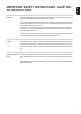
General EN-US IMPORTANT SAFETY INSTRUCTIONS - SAVE THESE INSTRUCTIONS These operating instructions contain important instructions for the inverter that must be followed during installation and maintenance of the inverter. The inverter is designed and tested according to international safety requirements, but as with all electrical and electronic equipment, certain precautions must be observed when installing and/or operating the inverter.
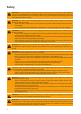
Safety WARNING! Incorrect operation and work performed incorrectly can cause serious injury and damage to property. Only qualified staff are authorized to install your inverter and only within the scope of the respective technical regulations. Do not start operation or carry out maintenance work until you have read the "Safety Instructions" chapter. WARNING! An electric shock can be fatal. Danger due to grid voltage and DC voltage from solar modules that are exposed to light.
CAUTION! Danger of damaging the inverter due to improperly connected terminals. Improperly connected terminals can cause thermal damage to the inverter and may cause a fire. When connecting the AC and DC cables, make sure that all terminals are tightened securely using the proper torque. CAUTION! Risk of fire due to incorrectly designed AC fuse.
NOTE! Form a min. 4 in. wire loop using all wires.. NOTE! To ground solar module frames or mounts, you must observe both the relevant instructions from the solar module manufacturer and national guidelines. NOTE! Follow general ESD guidelines when handling option cards. NOTE! Fronius will not bear any costs for loss of production, or installations, etc., which may arise due to a detected electric arc and its consequences.
CAUTION! Risk of damage to inverters and other live photovoltaic system components due to poor or unprofessional installation. Poor or unprofessional installation can cause overheating of cables and terminal connections and result in arcs. These can cause heat damage, which in turn may lead to fires.
6
FR CONSERVER LES CONSIGNES DE SÉCURITÉ IMPORTANTES DES PRÉSENTES INSTRUCTIONS DE SERVICE Généralités Les présentes Instructions de service contiennent des indications importantes relatives au l'onduleur, qui doivent être respectées lors de l'installation et de l'entretien de l'onduleur. L'onduleur a été construit et contrôlé en tenant compte des directives de sécurité internationales.
Sécurité AVERTISSEMENT ! Les erreurs de commande et les erreurs en cours d'opération peuvent entraîner des dommages corporels et matériels graves. La mise en service de l'onduleur ne peut être effectuée que par du personnel formé à cet effet et dans le cadre des directives techniques. Avant la mise en service et l'exécution de travaux d'entretien, lire les " Consignes de sécurité ". AVERTISSEMENT ! Une décharge électrique peut être mortelle.
AVERTISSEMENT ! Une connexion de conducteur de terre insuffisante peut entraîner de graves dommages corporels et matériels. Les vis du boîtier constituent une connexion de conducteur de terre appropriée pour la mise à la terre du corps de l'appareil. Il ne faut en aucun cas remplacer ces vis par d'autres vis qui n'offriraient pas ce type de connexion de conducteur de terre autorisée.
REMARQUE ! Ne relier la mise à la terre en aucun point avec la ligne DC négative ! Cette liaison est déjà réalisée à l'intérieur de l'onduleur. Si les lignes DC négatives sont raccordées aux bornes de raccordement DC ou, au préalable, à la terre, elles contournent le système de protection GFDI et empêchent l'onduleur d'identifier les courants de défaut.
ATTENTION ! Risque de détérioration des onduleurs et autres composants sous tension d’une installation photovoltaïque en raison de montages défectueux ou incorrects. Des montages défectueux ou incorrects peuvent entraîner une surchauffe des câbles et des connexions et également provoquer des arcs électriques. Les dégâts thermiques qui en résultent peuvent provoquer des incendies.
12
INFORMACIÓN DE SEGURIDAD IMPORTANTE CONSERVE ESTE MANUAL DE INSTRUCCIONES Este manual de instrucciones incluye instrucciones importantes para el inversor que deben cumplirse en relación con la instalación y el mantenimiento del inversor. El inversor ha sido diseñado y comprobado según las disposiciones de seguridad internacionales. Debido a sus componentes eléctricos y electrónicos, es necesario tener en cuenta determinadas medidas de precaución durante la instalación y el servicio del inversor.
Seguridad ¡ADVERTENCIA! El manejo incorrecto y los trabajos realizados de forma defectuosa pueden causar graves daños personales y materiales. La puesta en marcha del inversor solo debe ser efectuada por personal formado y en el marco de las disposiciones técnicas. Antes de la puesta en servicio y la realización de trabajos de mantenimiento, resulta imprescindible leer las indicaciones de seguridad. ¡ADVERTENCIA! Las descargas eléctricas pueden ser mortales.
¡PRECAUCIÓN! Riesgo de dañar el inversor debido a suciedad o agua en los bornes de conexión y en los contactos de la zona de conexión. Al taladrar, debe prestarse atención a que los bornes de conexión y los contactos en la zona de conexión no se ensucien ni humedezcan. El soporte mural sin la etapa de potencia no corresponde al tipo de protección de todo el inversor, por lo que no debe ser montado sin la etapa de potencia. Proteger el soporte mural durante el montaje frente a suciedad y humedad.
¡OBSERVACIÓN! ¡En ningún punto debe conectarse la puesta a tierra a la línea CC negativa! Esta conexión ya se ha realizado dentro del inversor. Si las líneas CC negativas se conectan a los bornes de conexión CC o si han sido conectadas previamente a la puesta a tierra, el sistema de protección GFDI evita esta situación e impide que el inversor pueda detectar corrientes de falta.
Prevención de Incendios A la hora de conectar cables CA y CC debe tenerse en cuenta lo siguiente: Apretar firmemente todos los bornes de conexión con el par indicado en el manual de instrucciones Apretar todos los bornes de conexión a tierra (PE / GND) con el par indicado en el manual de instrucciones, incluyendo los bornes de conexión a tierra libres No sobrecargar los cables Comprobar los cables respecto a daños y su tendido correcto Tener en cuenta las indicaciones de seguridad, el manual de instruccion
Fronius Galvo 208-240 Installation Help English (US) Français English (US) www.fronius.com/QR-link/4204260182EA Français www.fronius.com/QR-link/4204260182FR Español www.fronius.
Fronius Galvo 208-240 Installation = + - L1 N ~ = NEMA4X + - L1 N ~ = + - L1 N ~ = + - = L1 N + - ~ L1 N max. 11482 ft. 3500 m UDC max ft. (m) = + - L1 N ~ > 11482 ft. > 3500 m ~ > 9842 - 11482 ft. 430 V (> 3000 - 3500 m) > 8202 - 9842 ft. 480 V (> 2500 - 3000 m) > 6561 - 8202 ft. 540 V (> 2000 - 2500 m) 0 - 6561 ft.
6 in. 150 mm 8 in. 200 mm 4 in.
1 1 EN-US: brick /concrete wall FR: mur de briques / beton ES: pared de ladrillo / muro de hormigón 1 NO NEMA ENCLOSURE TYPE 1 2 3 Al / St 0.2 - 0.3 in.
1 1 Al / St 0.2 - 0.3 in. (6 - 8 mm) 1 min.
1 1 EN-US: Mounting to a metal carrier FR: Montage sur un support métallique ES: Montaje en un soporte de metal 23
1 1 ? EN-US: mast, pole, pile, ... FR: mât, pile, barre, ...
Knockouts METAL KNOCKOUTS Remove knockout-parts fallen into the connection area before hanging the inverter to the wall bracket! 1/2 in. (12.7 mm) 1/2 in. (12.7 mm) 3/4 in. 3/4 in. (19.05 mm) (19.05 mm) 3/4 in. (19.05 mm) 3/4 in. (19.05 mm) 1/2 in. ... DATCOM * 3/4 in. ... AC ~ / DC = 3/4 in. (19.05 mm) 3/4 in. (19.05 mm) 3/4 in. (19.05 mm) 1/2 in. (12.7 mm) 3/4 in. (19.05 mm) * ............
Appropriate Grids 208 V Delta No neutral conductor Setup: 208 208 V Delta: 120 V WYE Neutral conductor available L1 L1 120 V ° 20 8V 20 8 12 0 V ° V N ~ ~ ~ 0V L2 208 V L3 L2 120 ° 120 ° = = ~ 220 V Delta No neutral conductor Setup: 220 220 V Delta: 127 V WYE Neutral conductor available L1 127 V ° 0V 22 0 22 V ° 12 0 12 0 L3 V 12 ~ 7V L2 220 V 120 ° 120 ° = = ~ ~ 240 V Delta No neutral conductor Setup: 240 240 V: 120 V Stinger Neutral conductor available Setu
240 V: 120 V Split phase Neutral conductor available Setup: 240N 180 ° L1 N 120 V 120 V L2 240 V = ~ 27
Connection Diagram & Connection Area DC = (+) Fronius Galvo 208-240 DC = terminal block L2 L1 N DC = disconnect Grounding terminal DC = (-) PV frame ground Grounding electrode terminal * N L1 L2 Energymeter AC ~ distribution panel Lockable AC ~ disconnect switch Main grounding system DC = Disconnect Cu / Al Cu max. Class 4 Cu: min. AWG 14 - max. AWG 6 Al : AWG 6 DC = (+) DC = (-) AC ~ 15.93 lb-in / 1.33 ft. lb. / 1.8 Nm All terminals are suitable for multi conductor applications.
Wire Size (AWG) Wire Material 8AWG and 10 AWG Copper (CU) - stranded and solid 8AWG and 12 AWG Copper (CU) - stranded and stranded Copper (CU) - stranded and solid 8AWG and 14 AWG Copper (CU) - stranded and stranded Copper (CU) - stranded and solid 10AWG and 10 AWG Copper (CU) - stranded and stranded Copper (CU) - stranded and solid 10AWG and 12 AWG Copper (CU) - stranded and stranded Copper (CU) - solid and solid 10AWG and 14 AWG Copper (CU) - stranded and stranded Copper (CU) - solid and soli
AC ~ 1 1 3 OFF AC ~ > 10 in. (250 mm) GND L2 L1 N AC ~ 2 0.6 in. (15 mm) GND > 8 in. (200 mm) 1 2 AC ~ max. 20 A ** * 5x wire loop min. 4 in. (101.6 mm) 15.93 lb-in 1.33 ft. lb. 1.8 Nm * main grounding terminal ** grounding terminals, e.g.
Standard Solar Module Grounding on negative Pole EN-US: The inverter comes with a GFDI fuse for negatively grounded solar modules as standard. CAUTION when using ungrounded solar modules. Remove the GFDI fuse. + DC = (+) DC = (-) * = ~ N L1 L2 GND * GFDI Fuse, 1 A / 600 V / 41,0007,0187 (standard) FR: L'onduleur est équipé de série d'un fusible GFDI pour modules solaires dont le pôle négatif est raccordé à la terre.
DC = 1 1 DC = (-) DC = DC = (+) 1 2 1 2 1 1 2 3 0.6 in. (15 mm) 1 DC = (+) DC = (-) 2x 15.93 lb-in / 1.33 ft. lb / 1.8 Nm 1 wire loop min. 4 in. (101.6 mm) 1 4 5 ft. (m) UDC max > 9842 - 11482 ft. 430 V (> 3000 - 3500 m) > 8202 - 9842 ft. 480 V (> 2500 - 3000 m) > 6561 - 8202 ft. 540 V (> 2000 - 2500 m) 0 - 6561 ft.
33
Data communication and Solar Net Fronius Solar Net and Data Interface Fronius developed Solar Net to make these system add-ons flexible and capable of being used in a wide variety of different applications. Fronius Solar Net is a data network that enables several inverters to be linked to the system add-ons. Fronius Solar Net is a bus system with ring topology. Just one suitable cable is enough to provide communication between one or more inverter connected to Fronius Solar Net and a system add-on.
Designation (1) Switchable multifunction current interface (e.g. for power reduction function, interface to meter, measurement input, etc.) Pin 1 = measurement input: max. 20 mA, 100 Ohm measurement resistor (load impedance) Pin 2 = max. short circuit current 15 mA, max.
Designation (6) USB A socket for connecting a USB stick with maximum dimensions of 65 x 30 mm EN-US Item The USB stick can function as a datalogger for an inverter. The USB stick is not included in the scope of supply of the inverter. (7) Floating switch contact with mating connector max. 250 V AC / 4 A AC max. 30 V DC / 1 A DC max. AWG16 (1.
Any other Fronius Datamanagers must be removed and the unoccupied option card compartment sealed off using the blanking cover (42,0405,2020 - available from Fronius as an optional extra); alternatively, use an inverter without Fronius Datamanager (light version).
Communication de données et Solar Net Fronius Solar Net et le transfert de données Le Fronius Solar Net a été développé par Fronius pour une utilisation individuelle des extensions de système. Le Fronius Solar Net est un réseau de données permettant de relier plusieurs onduleurs aux extensions de système. Le Fronius Solar Net est un système de bus à topologie en anneau.
Désignation (1) Interface de courant multifonction interconnectable (par ex. pour fonction de réduction de puissance, interface de compteur, entrée de mesure, etc.). Broche 1 = entrée de mesure : max. 20 mA, résistance de mesure (charge) 100 Ohm Broche 2 = courant de court-circuit max. 15 mA, tension à vide max.
Pos. Désignation (5) DEL « Transfert de données » clignote lors de l'accès à la clé USB. Pendant ce laps de temps, la clé USB ne doit pas être retirée. (6) Connecteur USB A pour le raccordement d'une clé USB de taille maximale 65 x 30 mm. La clé USB peut jouer un rôle de datalogger pour un onduleur. La clé USB n'est pas comprise dans la livraison de l'onduleur. (7) Contact sans potentiel avec contre-fiche max. 250 V AC / 4 A AC max. 30 V DC / 1 A DC section de câble max.
FR IMPORTANT ! Puisque le Fronius Datamanager fonctionne comme un Datalogger, aucun autre Datalogger ne doit être présent dans le circuit Fronius Solar Net. Un seul Fronius Datamanager par circuit Fronius Solar Net ! Démonter tous les autres Fronius Datamanager et obturer le compartiment pour cartes d'option libre au moyen du cache disponible en option auprès de Fronius (42,0405,2020) ou utiliser un onduleur sans Fronius Datamanager (version light).
Comunicación de datos y Solar Net Fronius Solar Net y conexión de datos Fronius ha desarrollado Fronius Solar Net para facilitar la aplicación individual de las extensiones del sistema. Fronius Solar Net es una red de datos que permite vincular varios inversores con las extensiones del sistema. Fronius Solar Net es un sistema de bus con topología de circuito. Para la comunicación de uno o varios inversores conectados en Fronius Solar Net con una extensión del sistema, basta con un cable adecuado.
Pos. Descripción (1) Interfaz de corriente multifuncional conmutable (por ejemplo, para la función de reducción de potencia, interfaz con el contador, entrada de medición, etc.) Variante del modo de conexión 1: Contacto de señal para protección contra sobretensiones Pin 1: Pin 2: + Variante del modo de conexión 2: 4-20 mA Pin 1: + Pin 2: Utilizar el conector opuesto de dos polos incluido en el volumen de suministro del inversor para la conexión a la interfaz de corriente multifuncional.
Pos. Descripción (5) LED "Transmisión de datos" Parpadea durante el acceso a la memoria USB. En este tiempo no debe quitarse la memoria USB. (6) Zócalo USB A Para la conexión de una memorias USB con un máximo tamaño constructivo de 65 x 30 mm La memoria USB puede funcionar como un Datalogger para un inversor. La memoria USB no forma parte del volumen de suministro del inversor. (7) Contacto de conmutación libre de potencial con conector opuesto máx. 250 V CA / 4 A CA máx. 30 V CC / 1 A CC máx.
ES ¡IMPORTANTE! Como el Fronius Datamanager funciona como un Datalogger, no debe haber otro Datalogger en el circuito de Fronius Solar Net. ¡Solo un Fronius Datamanager por cada circuito de Fronius Solar Net! Desmontar los demás Fronius Datamanager y cerrar el compartimento de tarjetas opcionales libre con la cubierta ciega disponible como opción a través de Fronius (42,0405,2020) o utilizar un inversor sin Fronius Datamanager (versión "light").
DATCOM 1 1 2 1 4 x TX25 3 4 5 1 2 1 1 1 3 4 1 1 TX20 2 46 10.62 lb-in 0.89 ft. lb. 1.
1 1 5 6 1 1 1 7 5 3 8 22.13 lb-in 1.84 ft. lb 2.
1 1 11 12 42,0405,2019 1 1 TOP 1 1 3 CLICK ! 2 2 4.33 in. (110 mm) 1 1 13 14 2 1 ON OFF Lock 48 OUT 3 2 NO CABLE LOOP ! IN 2 x TX25 1 4 4 5 3 22.13 lb-in 1.84 ft. lb. 2.
Floating Switch Contact EN-US: To evaluate a GFDI fault, a floating switch contact is available at the backside of the inverter. FR: Pour évaluer une erreur GFDI, un contact sans potentiel est disponible à l'arrière de l'onduleur. ES: Para evaluar un error GFDI, un contacto de conmutación libre de potencial está disponible en la parte posterior del inversor. EN-US: Pin 1 = NC contact Pin 2 = common Pin 3 = NO contact (pins from top to bottom) 1 2 3 max. 250 V AC ~ / 4 A AC ~ max. 30 V DC = / 1 A DC = max.
Sealing up Conduits Outside NOTE! Condensation within the conduits can damage the inverter or components of the photovoltaic systems. EN-US: To avoid undesirable air circulation and condensation in the conduits, seal all conduits being used with a permanently elastic sealant, seal every incoming and outgoing conduit, seal both conduit ends.
Operation 1 1 1 1 ON OFF Lock ON OFF 4 2 x TX25 Lock 2 2 3 5 22.13 lb-in / 1.84 ft. lb. / 2.5 Nm 1 1 2 3 AC = ON 2 ON 1 3 OFF 1 4 Lock 22.13 lb-in 1.84 ft. lb. 2.5 Nm 2 1 1 4 5 CONFIG inst. EX V0.0.03 0x0001 61 1 62 1 1 6 CONFIG Country new 240N * V0.0.
1 1 1 SETUP Auto Daylightsaving 10 9 11 Grounding Mode 5x 4x 1 12 52 1 2 1 1 13 2 1 2
Anti-theft device 1 1 2 1 2 1 TX25 2 2 3 1 22.13 lb-in 1.84 ft. lb. 2.5 Nm TX25 EN-US: The padlock is not part of the scope of delivery for the inverter. 1 3 FR: Le cadenas n'est pas compris dans la livraison de l'onduleur. ES: El candado no está parte del volumen de suministro del inversor. 1 2 2 max 0.28 in.
Lock 1 1 2 1 1 1 * * max 0.28 in. (7 mm) EN-US: The padlock is not part of the scope of delivery for the inverter. 1 3 FR: Le cadenas n'est pas compris dans la livraison de l'onduleur. ES: El candado no está parte del volumen de suministro del inversor. 1 * * 54 max 0.28 in.
+ USB Firmware Update 1 2 2 3 4 4 5 55
BASIC Menu 1 1 1 2 1 6x 6 1 4 MPP Tracker 1 USB Eventlog SMS / Relay Grounding Settings Insulation Settings 56 3 1 5x BASIC Menu: MPP Tracker 1 USB Eventlog SMS / Relay Grounding Settings Insulation Settings Temperature Warning TOTAL Reset 5x 2 1
Field Adjustable Trip Points Setup 208 V Setup 220 V UAC [V] Clearing Time [s] Clearing Time [cyl] UAC [V] Clearing Time [s] Clearing Time [cyl] U < 50% 104 0.16 9 110 0.16 9 50 ≤ U < 88 % 183 2 118 194 2 118 110 < U < 120 % 229 1 58 242 1 58 U ≥ 120 % 249 0.16 9 264 0.16 9 UImin adjustable 104 - 198 0.016 - 21.0 1 - 1258 104 - 209 0.016 - 21.0 1 - 1258 UImax adjustable 218 - 288 0.016 - 21.0 1 - 1258 231 - 288 0.016 - 21.0 1 - 1258 UOmax adjustable 218 - 288 0.016 - 4.
Trip Limits NLMON (127 V) Trip Limits NLMON (120 V) UAC [V] Clearing Time [s] Clearing Time [cyl] UAC [V] Clearing Time [s] Clearing Time [cyl] U < 50% 64 0.16 9 60 0.16 9 50 ≤ U < 88 % 112 2 118 106 2 118 110 < U < 120 % 139 1 58 132 1 58 U ≥ 120 % 152 0.16 9 144 0.16 9 UImin adjustable 60 - 121 0.016 - 21.0 1 - 1258 60 - 114 0.016 - 21.0 1 - 1258 UImax adjustable 133 - 152 0.016 - 21.0 1 - 1258 126 - 152 0.016 - 21.0 1 - 1258 UOmax adjustable 133 - 152 0.016 - 4.
Reconnection Reconnection Time 300 s Reconnection Time adjustable 5 - 900 s Fmax reconnect value < 60.5 Hz Fmin reconnect value > 59.3 Hz Umin reconnect value U > 88 % Umax reconnect value U < 106 % Fmin reconnect value adjustable 45.00 - 65.00 Hz Fmax reconnect value adjustable 45.00 - 65.
Serial Number Sticker for Customer Use Application example * 2 1 ** ? Serial No.
Fronius Technical Support Fronius USA LLC Solar Electronics Division 6797 Fronius Drive Portage, IN 46368 USA E-Mail: pv-us@fronius.com http://www.fronius-usa.com Fronius Canada Ltd. 2875 Argentia Road, Units 4,5 & 6 Mississauga, ON L5N 8G6 Canada E-Mail: pv-sales-canada@fronius.com http://www.fronius.ca Tel.: 877-Fro-nius (376-6487) Fax: 219-734-5502 Tel.: +1 905 288 2100 Fax: +1 905 288 2101 Fronius Mexico S.A. de C.
Fronius Worldwide - www.fronius.com/addresses Fronius International GmbH 4600 Wels, Froniusplatz 1, Austria E-Mail: pv-sales@fronius.com http://www.fronius.com Fronius USA LLC Solar Electronics Division 6797 Fronius Drive, Portage, IN 46368 E-Mail: pv-us@fronius.com http://www.fronius-usa.com Under http://www.fronius.