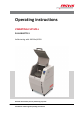
Operating instructions VIBRATING CUP MILL PULVERISETTE 9 Valid starting with: 09.
Fritsch GmbH Milling and Sizing Industriestraße 8 D - 55743 Idar-Oberstein Telephone: +49 (0)6784/ 70-0 Fax: +49 (0)6784/ 70-11 email: info@fritsch.de Internet: www.fritsch.
Certifications and CE conformity Certifications and CE conformity Certification Fritsch GmbH has been certified by the TÜV-Zertifizierungsgemeinschaft e.V. An audit certified that Fritsch GmbH conforms to the requirements of the DIN EN ISO 9001:2008. CE Conformity The enclosed Conformity Declaration lists the guidelines the FRITSCH instrument conforms to, to be able to bear the CE mark.
Table of contents Table of contents 1 Basic structure............................................................................... 6 2 Safety information and use........................................................... 7 2.1 Requirements for the user..................................................... 7 2.2 Scope of application............................................................... 7 2.2.1 Operating principle............................................................. 8 2.
Table of contents 6.1.3 Dry grinding....................................................................... 6.1.4 Wet grinding (grinding in a suspension)........................... 6.1.5 Filling the grinding set....................................................... 6.1.6 Clamping the grinding set................................................. 6.2 Menu navigation.................................................................. 6.2.1 Invoke/Save program....................................................
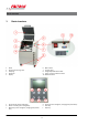
Basic structure 1 Basic structure 1 2 3 4 5 Hood Eccentric tensioning roller Clamping Hood lock Display 6 7 8 9 10 Main switch Control panel Height-adjustable device feet Excess current protection switch RS232 interface a b c Up arrow key (menu navigation) Down arrow key (menu navigation) Minus key (menu navigation, changing the parameters) d e f Plus key (menu navigation, changing the parameters) Start key Stop key -6-
Safety information and use 2 Safety information and use 2.1 Requirements for the user This operating manual is intended for persons assigned with operating and monitoring the Fritsch PULVERISETTE 9. The operating manual and especially its safety instructions are to be observed by all persons working on or with this device. In addition, the applicable rules and regulations for accident prevention at the installation site are to be observed.
Safety information and use 2.2.1 Operating principle The vibrating cup mill functions according to the principle of vibratory milling. This means that the grinding set is clamped on a vibrating structure and the grinding bodies (puck and rings) in it are accelerated by centrifugal forces and the grinding stock is comminuted by impact and friction.
Safety information and use Neither compliance with this manual nor the conditions and methods used during installation, operation, use and maintenance of the PULVERISETTE 9 can be monitored by Fritsch GmbH. Improper execution of the installation can result in property damage and thus endanger persons.
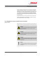
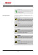
Safety information and use ENVIRONMENT! This symbol and keyword combination points out a possibly hazardous situation that can result in environmental damage if not avoided. Special safety information To call attention to specific hazards, the following symbols are used in the safety information: DANGER! This symbol and keyword combination points out a directly hazardous situation due to electrical current. Ignoring information with this designation will result in serious or fatal injury.
Safety information and use Safety information in the procedure instructions Safety information can refer to specific, individual procedure instructions. Such safety information is embedded in the procedure instructions so that the text can be read without interruption as the procedure is being carried out. The keywords described above are used. Example: 1. Loosen screw. 2. CAUTION! Risk of entrapment at the lid. Close the lid carefully. 3. Tighten screw.
Safety information and use 2.5 Device safety information Please observe! n Only use original accessories and original spare parts. Failure to observe this instruction can compromise the safety of the machine. n Accident-proof conduct is to be strictly followed during all work. n Comply with all currently applicable national and international accident prevention guidelines.
Safety information and use 2.6 Protective equipment Protective equipment is to be used as intended and may not be disabled or removed. All protective equipment is to be regularly checked for integrity and proper functioning. The vibrating cup mill is equipped with a safety lock that also protects the operator. It locks the hood (1) during operation and prevents the vibrating cup mill from being started when the hood is open: n The hood cannot be opened during operation.
Safety information and use 1. Use the supplied triangular key to open the door on the right side of the device. 2. A red release grip can be found there that is attached to the housing by a cylinder screw. 3. Use a SW 4 hex key to loosen and remove the cylinder screw that holds the release grip. Put the screw aside. 4. Take a hold of the release grip and slowly pull the lock of the hood open by the cable. 5.
Safety information and use 2.8 Electrical safety 2.8.1 General information n After the STOP key (f) is pressed, the vibrating cup mill runs out. Once the motor stands still, the hood (1) can be opened. n When using the grinding set made of agate, the speed is limited automatically to 750 rpm. n Switch off (0) the main switch (6) if the mill will be idle for a longer period of time (e.g. overnight). 2.8.
Technical data 3 Technical data 3.1 Dimensions 1220 x 770 x 760 mm (height x depth x width) 3.2 Weight 267 kg (without grinding set) 280 kg (with 250 ml grinding set made of tungsten carbide) 3.3 Operating noise Emissions value of workplace according to DIN EN ISO 3746:2005 LPa = 81 dB(A). The value was measured in a sound-proof room with a 250 ml steel grinding set at 1500 rpm. The value changes depending on the grinding set used or the grinding stock used and set speed.
Technical data 3.7 Electrical fuses in the control device n Excess current protection switch (9) 15 A (drawer on the side) (See Ä Chapter 9.1 ‘Checklist for troubleshooting’ on page 37). 3.8 Material n The feed amount depends on the size of the grinding set used and is maximum 50, 100 or 250 ml. n The feed size also depends on the type and size of the grinding set and is maximum 7 or 12 mm. 3.9 Final fineness Up to 10 - 20 µm.
Installation 4 Installation 4.1 Transport The device is delivered on a transport pallet with a wooden cover. We recommend using a forklift or pallet truck for transporting the packed device. DANGER! Do not step under the transport pallet during transport. WARNING! Improper lifting can lead to personal injury or property damage. The machine is only to be lifted with suitable equipment and by qualified personnel. The guarantee excludes all claims for damage due to improper transport. 4.
Installation n Lift the vibrating cup mill off the transport pallet. The mill stands on two hollow profiles with 4 device feet (8). It can be lifted by a fork lift and taken from the transport pallet. n Place the vibrating cup mill on a flat, stable surface of an interior room. It does not have to be fastened to the surface. NOTICE! Never operate PULVERISETTE 9 while it is standing on the transport pallet! n Make sure that the vibrating cup mill is easily accessible.
Installation Remove the securing plates! 3. Afterwards, press the two supplied plastic plugs (g) into the mounting bore holes of the transport securing devices. 4. Save the transport securing devices. 4.5 Ambient conditions WARNING! Mains voltage! – The device may only be operated indoors. – The surrounding air may not carry any electrically conductive dust. – Maximum relative humidity 80% for temperatures up to 31°C, linearly decreasing down to 50% relative humidity at 40°C.
Installation Operate the vibrating cup mill only with a grinding set! n Plug the supplied power cord to the right side of the device. n Switch on (I) the main switch (6) on the right-hand side. n You can load and start the mill now as described in Ä Chapter 6 ‘Using the device’ on page 23. NOTICE! Fritsch mills are speed controlled. The devices are equipped for this with frequency converters.
Initial start-up 5 Initial start-up Perform initial start-up only after all work as described in Ä Chapter 4 ‘Installation’ on page 18 has been carried out. 5.1 Switching on Switch main switch (6) to I. 5.2 Function check NOTICE! Never operate the device without grinding stock, otherwise the grinding set can be damaged. n Open the hood (1). n Fill the grinding set half way with sand and clamp in (see Ä Chapter 6 ‘Using the device’ on page 23). n Close hood.
Using the device 6 Using the device CAUTION! Before starting the machine, make sure that the grinding set has been clamped correctly and that there are no loose parts inside the device. Failure to observe this will render void the guarantee, and releases us from liability for any resulting damage to the device as well as for any resulting personal injury.
Using the device 6.1 Preparing for grinding Preselect the speed, grinding duration and possible pause times and repeats. A grinding duration of 2 ‐ 4 minutes is sufficient in most cases to achieve a satisfactory grinding result. A longer grinding duration often does not result in a grinding progress for a smaller final fineness. When dry grinding for a longer period, the grinding stock cements to the grinding bodies and they are then rather difficult to clean. 6.1.1 6.1.
Using the device 6.1.3 Dry grinding Below a particle size of approx. 20 µm, the surface forces prevail and the material to be ground starts to "stick". Additional dry comminution can be achieved by adding surface-active substances to the material to be ground. Examples (maximum amount to be added in mass%) n n n n 6.1.4 Stearic acid 2-3% Aerosil (fine-particle silicic acid) 0.
Using the device CAUTION! Burn hazard! The grinding bowl can become hot during long grinding periods. Allow for cooling time after grinding. Wear safety gloves! 6.1.5 Filling the grinding set Filling quantity maximum as specified useable volumes (50, 100 or 250 ml). Filling quantity minimum 30 % of specified useable volumes. 6.1.6 1. Place all grinding bodies with the rounded edge downwards in the empty grinding cup. 2. Fill grinding stock into the grinding cup between the grinding bodies. 3.
Using the device 3. Grip the clamp lever directly over the turning point and turn forward. 4. Grip the clamp lever at the front handle and push all the way to the back. The eccentric is moved over its lowest point and clamps the grinding set tight. 5. A small lever on the right side of the clamp lever presses a safety switch that releases the device only when the clamping device (3) is actuated. In case the clamping device gets loose during the milling, the device shuts down immediately.
Using the device 10. Grip the clamp directly over the turning point then and turn it all the way back. 11. The grinding set is pressed upward out of the gap by the ball pressure pieces and can be pulled forward towards the body by the grips. 12. It can happen that the grinding set sticks to the rubber plate and cannot be moved forward because of that. A thin, firm object (such as a knife) can be slid between the rubber plate and the grinding set to loosen the rubber plate.
Using the device Use the arrow keys (a,b) to switch between the individual parameters. The + / - keys (c,d) are used to change the values of the parameters. The set parameters are saved by pressing the START key (e). The saved parameters are available when the main switch (6) is switched on again. The device can be put into operation by pressing the Start key (e) only from this menu field.
Using the device Program change 1..9 with the + /- keys (c,d); the respectively saved data appears in the Program display field. The Active display field shows the parameter data from the Parameter menu. Once the Load menu item is active and one of the keys + (d) or - (c) is pressed, the data from the program No. X is loaded and displayed in the Active display field. Once the Save menu item is active and one of the keys + (d) or - (c) is pressed, the current data is saved in the program No.
Using the device 6.2.2 Information display This display shows n the total operating hours (without pause times). n the current drive output during operation. n the version of the controller software. Changes/Entries are not possible here. 6.2.3 Check/Setup display Activate the language selection with the arrow keys (a,b). Use the + / - keys (c,d) to change the display language. 6.2.4 Error display Operation errors or system messages are reported here in an own display.
Using the device 6.3.1 Speed The speed of the drive motor (= oscillation frequency of the grinding set) can be set between 600 and 1500 rpm in steps of 50. The speed is constantly readjusted in narrow limits (+/- 1 %), so that the grinding results are very well reproducible. In particular, it is possible with heavy grinding sets that high speeds cannot be reached due to drive overload. This is indicated by a reduced speed display.
Using the device 6.4 Switching on the vibrating cup mill Once the filled grinding set has been clamped in securely and the hood (1) has been closed, the vibrating cup mill can be switched on. 1. Select the times of the grinding duration. 2. Press the START key (e) on the control panel (7). 3. The hood (1) is locked and the vibrating cup mill starts. 4. The timer starts running and the remaining time is indicated on the display (5).
Cleaning 7 Cleaning DANGER! Mains voltage! – Before beginning with cleaning work, disconnect the mains plug and protect the device against being unintentionally switched back on! – Do not allow any liquids to flow into the device. – Indicate cleaning work with warning signs. – Put safety equipment back into operation after cleaning work. 7.
Maintenance 8 Maintenance DANGER! Mains voltage – Before beginning with maintenance work, unplug the mains plug and protect the device against being unintentionally switched back on again! – Indicate maintenance work with warning signs. – Maintenance work may only be performed by specialised personnel. – Put safety equipment back into operation after maintenance or repair work. We recommend keeping a safety logbook Ä Chapter 13 ‘Safety logbook’ on page 43, where all work (maintenance, repairs......
Maintenance Functional part Wear bar holder Task Test Maintenance interval Fasten the grinding set securely Visual inspection of rubber plate; replace if worn, nominal thickness 5 +/0.4mm or place spacer (09.4133.09) underneath. Check before every use; replace after 50 hours of operation Secure seating of the grinding set and protection of the holder Visual inspection of the wear bar; replace if worn Replace after 50 hours of operation 8.
Repairs 9 Repairs DANGER! Mains voltage! – Before beginning with repair work, unplug the mains plug and protect the device against being unintentionally switched back on. – Indicate repair work with warning signs. – Repair work may only be performed by specialised personnel. – Put safety equipment back into operation after maintenance work. 9.
Disposal 10 Disposal It is hereby confirmed that FRITSCH has implemented the directive 2002/95/EC of the European Parliament and Council from 27th January 2003 for the limitation of the use of certain dangerous substances in electrical and electronic devices.
Guarantee terms 11 Guarantee terms Guarantee period As manufacturer, FRITSCH GmbH provides – above and beyond any guarantee claims against the seller – a guaranty valid for the duration of two years from the date of issue of the guarantee certificate supplied with the device. Within this guarantee period, we shall remedy all deficiencies due to material or manufacturing defects free of charge. Rectification may take the form of either repair or replacement of the device, at our sole discretion.
Guarantee terms Costs not covered by the guarantee This guarantee excludes any costs for transport, packaging or travel that accrue in the event the product must be sent to us or in the event that one of our specialist technicians is required to come to your site. Any servicing done by persons not authorised by us and any use of parts that are not original FRITSCH accessories and spare parts will void the guarantee.
Exclusion of liability 12 Exclusion of liability Before using the product, be sure to have read and understood this operating manual. The use of the product requires technical knowledge; only commercial use is permitted. The product may be used exclusively within the scope of applications set down in this operating manual and within the framework of guidelines put forth in this operating manual and must be subject to regular maintenance.
Exclusion of liability Fritsch GmbH excludes any liability, warranty, or other obligation to compensate for damages, regardless of whether this liability, warranty, or other obligation is explicit or implicit, contractual or arising from unlawful acts or prescribed contractually, by law, or otherwise.
Safety logbook 13 Date Safety logbook Maintenance / Repair Name - 43 - Signature
Safety logbook Date Maintenance / Repair Name - 44 - Signature
Safety logbook Date Maintenance / Repair Name - 45 - Signature
Index 14 Index A M Accident prevention . . . . . . . . . . . . . . . . . . . . . . . . 7 Ambient conditions . . . . . . . . . . . . . . . . . . . . . . . 20 Authorised persons . . . . . . . . . . . . . . . . . . . . . . . . 7 Maintenance . . . . . . . . . . . . . . . . . . . . . . . . . . . . 35 Materials . . . . . . . . . . . . . . . . . . . . . . . . . . . . . . 17 Menu navigation . . . . . . . . . . . . . . . . . . . . . . . . . 28 B O Basic structure . . . . . . . . . . . . . . . . . . . . . .
© 2014 Fritsch GmbH Milling and Sizing Industriestraße 8 D - 55743 Idar-Oberstein Telephone: +49 (0)6784/ 70-0 Fax: +49 (0)6784/ 70-11 email: info@fritsch.de Internet: www.fritsch.