Instruction manual Gas-Pressure- and TemperatureMeasuring-system „GTM II“ for Laboratory-Planetary Mill “pulverisette 5” and Laboratory-Mono-Mill “pulverisette 6” and Vario-Planetary-Mill “pulverisette 4”
Fritsch GmbH Laborgerätebau Industriestrasse 8 D - 55743 Idar-Oberstein Phone: Fax: E-Mail: Internet: +49 (0)6784/ 70-0 +49 (0)6784/ 70-11 info@fritsch.de http://www.fritsch.de Fritsch GmbH, Laborgerätebau has been certified by the TÜVZertifizierungsgemeinschaft e.V. on June 24, 1994. An audit has certified, that Fritsch GmbH fulfills DIN EN ISO 9001. The enclosed declaration of conformity names the directives, which the GTM-system corresponds to. This permits us to mark the instrument with the CE-Sign.
Table of contents page 1 General Information / Introduction .........................................1 1.1 1.2 1.3 Notes about the Operating Manual ...................................................... 1 Explanations of the signs on the instrument and in the operating manual ........................................................................ 1 Brief Description of the Instrument ....................................................... 2 1.3.1 1.3.2 1.3.3 1.3.4 Applications ..........................
1 General Information / Introduction 1.1 Notes about the Operating Manual • The copyrights to these technical documents remain with Fritsch GmbH, Manufacturer of Laboratory Instruments. • These operating instructions are not to be reprinted or copied without express permission of Fritsch GmbH. • Please study these instructions carefully before operation. • All operators must be familiar with the contents of the operating instructions.
1.3 Brief Description of the Instrument 1.3.1 Applications The Measuring System GTM grasps simultaneously gas pressure and temperature in the grinding-bowl during the grinding in Planetary Mills. This allows a variety of statements to the description of the running comminuting, mixing, activating, amorphysing or phase-conversion processes. • The measured gas-pressure gives information based on the temperature-alterations in the grinding-bowl.
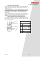
1.3.3 The measure principle The measure principle is based on it that pressure and temperature are directly proportional in an ideal gas (volumes and mass of the gas is steadily p = const * T). The transition of the process-heat of the powder on the gas takes place on reason the big powder-gas-contact-surface and the deep stirring when grinding directly, so that is to be registered temperature-alterations in the powder as pressure-alterations, approximately without timepostponement.
1.4 Technical data The evaluation software runs with WINDOWS 95/98/ME/NT40/2000© operating systems Dimensions receiver 1100 x 830 x 830 mm ( h x w x d) GTM1: Pressure measure-range1 0kPa – approx. 400kPa GTM1: Pressure measure-range2 approx. 20kPa - 400kPa GTM2: Pressure measure-range 0kPa – approx.
1.5 General Safety Instructions • The instrument can only to be used for the purpose described • Use only original accessories and original spare parts. Failure to do so may result in dangerous situations. • The operators must be familiar with the contents of the operating instructions. To this end, for example, the operating instructions must remain close by the instrument. • Do not remove labels • At all times keep in mind strict safety precautions while operating the instrument.
1.6 Electrical Safety Please pay attention to the input voltage of the receivers! Please plug the cables only into the correct sockets. 1.7 Operators • No one other than authorized persons should operate the instrument and it must be serviced and repaired by trained specialists. • No one suffering from medical problems or who are under the influence of medications, drugs, alcohol or suffer from overtiredness should be permitted to operate the instrument. 2 Installation 2.
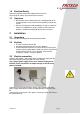
2.4 Loading of the battery in the transmitter (accu in transmitter unit) 2.4.1 voltage drop warning • • In case that the voltage drops below a set value, the computer software will report “recharge accu/battery”. After this message appears, the transmitter unit can still measure for a few hours. Accumulators will still have about 2/3 of the original charge.
2.4.3 Accumulator-lifespan • • • 2.5 The lifespan of the accumulators decreases with overheating of the transmitter unit. The accumulators should preferably be fully empty before recharging. The transmitter accumulators can be recharged about 1000 times if properly used. Start-up of the transmitter group • Loosen screws of transmitter unit of grinding-bowl • Plug in the switch-plug or loading cable into the socket of the transmitter unit.
2.6 Software installation 2.6.1 Prerequisites for the installation of the software • Common PC with MS-Windows (95 or higher) operating system • a serial interface with at least 19200 bauds transfer rate • Disk drive 3 ½“HD 2.6.2 Software-installation • Start the PC and the Windows operating system • Put in diskette 1 of GTM-System software • Execute a:\setup.exe and follow the installation instructions of the program. • Detailed step by step instructions can be found in attachment A1. 2.6.
2.7.1 Menu Options / configuration broadcast-unit • Serial number: Can only be changed when administrator modus is being activated. • Stand by: Time period till transmitter unit is being switched off for energy saving reasons. Only in case of significant measuring changes will further data transfer occur. • Survey transmission: After the period of (stand by) x (survey transmission.) data will be exchanged on a cyclic basis, even if equal values exist.
2.7.2 Setup – Configuration Set values in the configuration must be transmitted to the transmitter unit for activation. Connect the transmitter unit and the receiver using the loading cable. Pay attention to the receiver channel which had been selected in the configuration. In the next Step you activate with Measurement / Connection the interface. Thereafter you select under Measurement / Setup the transmitter tool “Setup broadcast-unit”.
3 Execution of Measurement 3.1 Filters • • • • Loosen the two slotted screws (under the transmitter unit). Remove plate Place filters (after delivery, a filter is already in place) Tighten screws of plate Use the transmitter unit only with a filter. Generally, change the filter if you us different materials when comminuting. Check the filter after each measurement and change it if necessary. 3.2 Execution of Measurement 1. 2. 3. 4. 5. 6. Test: • Start-up switches of the transmitter unit.
Mass balance may be made by: volume of the grinding bowl (ml) material weight without grinding balls and sample (gr.) order number stainless 3300 50.2100.00 steel tungsten 250 5000 50.2080.00 carbide The weight difference to the GTM II system incl. grinding balls and sample may be balanced with e.g. sand. Switch on receiver and PC Start the GTM II program 250 7. 8. 3.2.1 Transmitting of measuring values • Press this button to activate the connection to the receiver.
• With „CHECK IN“ you are being reminded to pull the plug out of the transmitter unit. Doing so will activate it and the data transfer to the receiver will commence. • The receipt of the measuring data will be indicated by the yellow LED on the receiver (yellow indication will change the switch position at intervals, depending on configuration). • Setting of speed and milling time, container with transmitter unit fit into the container mounting.
3.2.2 Ending Measuring • Select from the menu Measurement the command Close or press the button close recording (arrow). • Switch off the mill • Leave the grinding bowls in the mill to cool off. • Switch off transmitter unit - plug-in switch plug or charging cable in transmitter unit or recharge accumulators on receiver: plug-in charge cable on transmitter unit and receiver. • Take the grinding bowls out of the mill when cooled off • Clean grinding bowl, balls and filter cover if necessary.
4 Measurement evaluation Measuring values and additional information, which has been saved in ASCII-format may be used for further evaluation and calculation in the spreadsheet EXCEL or similar. You find in the protocol-head of the measurement-file: • general information, • the additional information and • the time and measurements in table-form. Example of a GTM-file: GTM-Daten V 02.
5 Detailed information 5.1 GTM Software The updating of the diagram during the measurement takes place within a second after arriving of new measurements. Measuring data is not joined at the time-axis but is represented by new displaying of the time-axis. On some older computers, the picture construction can be very slow with many measuring points. To use nevertheless multitasking put the program into the background (time for picture construction is no longer necessary) 5.
5.2.2 Stand by with configuration Stand by, extends the operation time of the transmitter unit with one accumulator-charge. In stand-by no measurements are taken and energy is being saved in the transmitter unit. If a measurement-alteration takes place after stand-by, the different criterions during stand-by are being adapted by the automatic measuring speed adaptation. 5.2.3 Automatic measuring speed adaptation The last three measured measurements are set aside in a shift register.
7 Maintenance Before working on the appliance disconnect from mains! The GTM system is maintenance-free, in general. Nevertheless, you should heed some hints: • Clean the O-rings and grooves after each application with soap-water and a rag. • Replace squashed or torn down dense-rings. • Use up the transmitter accumulators till fully empty before recharging. • Clean grinding-bowls, grinding balls and the filter-cover of any residues.
9 Troubleshooting Checklist Malfunction Light POWER is off Display "Receive" does not blink Possible cause No connection to power Switch is off Fuse Transmitter unit off Transmitter unit off transmitter is in standby or measurement is constant momentarily Distance of transmitter to receiver is too great Plug is properly in sockets Charging-light doesn't blink when charging cable is being plugged in On the screen Interface cable to the no measurePC is loose ments are shown, although Measurement hasn't R
11 A1 11.1 Installation manual Software GTM II Analysis software runs with WINDOWS 95/98/ME/NT40/2000© operating systems 11.1.1 Installation steps: 1. Slide the installation disk: Software GTM II disk 1‘ into the disk drive. 2. Initiate the command Start / Execute / a:setup / OK 3. Other programs closed? 4. License agreement GTM-System Æ next Æ Yes.
5. Installation directory can be changed with Browse Æ next 6. 6. Program file may be changed Æ next 7.
8. Installation of files is running 9. Program file and icon 10.