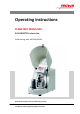
Operating instructions PLANETARY MONO MILL PULVERISETTE 6 classic line Valid starting with: 06.
Fritsch GmbH Milling and Sizing Industriestraße 8 D - 55743 Idar-Oberstein Telephone: +49 (0)6784/ 70-0 Fax: +49 (0)6784/ 70-11 email: info@fritsch.de Internet: www.fritsch.
Certifications and CE conformity Certifications and CE conformity Certification Fritsch GmbH has been certified by the TÜV-Zertifizierungsgemeinschaft e.V. An audit certified that Fritsch GmbH conforms to the requirements of the DIN EN ISO 9001:2008. CE Conformity The enclosed Conformity Declaration lists the guidelines the FRITSCH instrument conforms to, to be able to bear the CE mark.
Table of contents Table of contents 1 Basic structure............................................................................... 7 2 Safety information and use........................................................... 8 2.1 Requirements for the user..................................................... 8 2.2 Scope of application............................................................... 8 2.2.1 Operating principle............................................................. 9 2.2.
Table of contents 6 7 Using the device........................................................................... 6.1 Choice of grinding bowls and grinding balls........................ 6.1.1 Size of the grinding balls................................................... 6.1.2 Number of balls per grinding bowl (independent of the material quantity)............................................................. 6.1.3 Calculated weight of a ball................................................ 6.
Table of contents 8 Cleaning........................................................................................ 50 8.1 Grinding elements................................................................ 50 8.2 Mill....................................................................................... 50 9 Maintenance................................................................................ 51 10 Repairs.........................................................................................
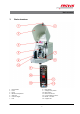
Basic structure 1 1 2 3 4 5 6 7 Basic structure Hood handle Latch Hood Membrane keyboard Safe-Lock Counter weight Lock 8 9 10 11 12 13 14 -7- Bowl holder Voltage rotary switch Main switch Mains connection Circuit breaker 2x 10 A T RS232 - interface Support disc
Safety information and use 2 Safety information and use 2.1 Requirements for the user This operating manual is intended for persons assigned with operating and monitoring the Fritsch of the PULVERISETTE 6. The operating manual and especially its safety instructions are to be observed by all persons working on or with this device. In addition, the applicable rules and regulations for accident prevention at the installation site are to be observed.
Safety information and use 2.2.1 Operating principle The grinding stock is crushed and ground by grinding balls in a grinding bowl. The centrifugal forces resulting from the rotation of the grinding bowls around their own axes and from the rotating support disc (14) influence the contents of the grinding bowl consisting of grinding stock and grinding balls.
Safety information and use By using the of the PULVERISETTE 6 the customer agrees with this and recognizes that defects, malfunctions or errors cannot be completely excluded. To prevent risk of damage to persons or property or of other direct or indirect damage, resulting from this or other causes, the customer must implement sufficient and comprehensive safety measures for working with the of the PULVERISETTE 6.
Safety information and use ENVIRONMENT! This symbol and keyword combination points out a possibly hazardous situation that can result in environmental damage if not avoided. Special safety information To call attention to specific hazards, the following symbols are used in the safety information: DANGER! This symbol and keyword combination points out a directly hazardous situation due to electrical current. Ignoring information with this designation will result in serious or fatal injury.
Safety information and use Safety information in the procedure instructions Safety information can refer to specific, individual procedure instructions. Such safety information is embedded in the procedure instructions so that the text can be read without interruption as the procedure is being carried out. The keywords described above are used. Example: 1. Loosen screw. 2. CAUTION! Risk of entrapment at the lid. Close the lid carefully. 3. Tighten screw.
Safety information and use 2.5 Device safety information Please observe! n Only use original accessories and original spare parts. Failure to observe this instruction can compromise the safety of the machine. n Accident-proof conduct is to be strictly followed during all work. n Comply with all currently applicable national and international accident prevention guidelines.
Safety information and use 2.6 Protective equipment Protective equipment is to be used as intended and may not be disabled or removed. All protective equipment is to be regularly checked for integrity and proper functioning. For start-up, the hood (3) has to be closed. The hood (3) is locked: n without mains connection n during operation The hood (3) can only be opened, if the mill's drive is at standstill. 2.6.
Safety information and use CAUTION! The imbalance switch can be disabled at your own risk. The Fritsch company will give no guarantee for damage resulting from disabling of the imbalance switch! NOTICE! Change these settings only after all work as described in Ä Chapter 4 ‘Installation’ on page 20 has been carried out! In the default setting of the imbalance switch, it is acti‐ vated! Activation / deactivation of the imbalance switch in Setup mode: 1.
Safety information and use 3. If POWER SUPPLY is flashing, the device is in setup mode. If POWER SUPPLY is not flashing, repeat the procedure. 4. NOTICE! In the display above the right "-" button (x) in the TIMER field, there must be a minus sign. That activates the imbalance switch and prevents a drift of the device and possible damage to the device resulting from it. 5. To save and end setup mode, press the STOP button. 2.7 Hazardous points CAUTION! – Crushing hazard when closing the hood (3).
Safety information and use CAUTION! Risk of burning! The grinding bowls can be very hot after grinding. Wear protective gloves! 2.8 Electrical safety 2.8.1 General information n The main switch (10) separates the device from the mains on two poles. n Switch off the main switch (10) if the planetary mono mill is down for a longer period of time (e.g. overnight). 2.8.
Technical data 3 Technical data 3.1 Dimensions 500 x 370 x 530 mm (height x width x depth) 3.2 Weight Net: 63 kg Gross: approx. 90 kg 3.3 Operating noise Emissions value of workplace according to DIN EN ISO 3746:2005 is up to 85dB (A). The value fluctuates strongly, depending on the speed, the grinding stock, and the type of grinding bowl and grinding balls. 3.
Technical data 3.7 Electrical fuses n Circuit breaker (12): 2 x 10 A T n Micro-fuse 10 A T in the frequency converter 3.8 Material n Maximum feeding size approx. 10 mm n Maximum feeding amount 225 ml 3.
Installation 4 Installation 4.1 Transport The device is delivered on a transport pallet with a wooden cover. We recommend using a forklift or pallet truck for transporting the packed device. DANGER! Do not step under the transport pallet during transport. WARNING! Improper lifting can lead to personal injury or property damage. The machine is only to be lifted with suitable equipment and by qualified personnel. The guarantee excludes all claims for damage due to improper transport. 4.
Installation 4.3 Setting up DANGER! Do not step under the transport pallet during transport. CAUTION! The weight of the planetary mono mill is approx. 67 kg! CAUTION! Crushing hazard! Always lift with 2 persons. Hold the bottom edge of the housing when lifting the device. CAUTION! Never operate the planetary mono mill while it is standing on the transport pallet! n Lift the mill from the transport pallet with at least 2 persons. n Place the mill on a flat, stable surface.
Installation 4.4 Ambient conditions WARNING! Mains voltage! – The device may only be operated indoors. – The surrounding air may not carry any electrically conductive dust. – Maximum relative humidity 80% for temperatures up to 31°C, linearly decreasing down to 50% relative humidity at 40°C. n The room temperature has to stay between 5 - 40°C. n Altitudes up to 2000 m n Degree of pollution 2 according to IEC 664. 4.
Installation The mains voltage has been set at the factory to that of the specific country. The mains voltage only has to be adjusted if it deviates from the value on the type plate. If adjustment is necessary, proceed as in Ä Chapter 4.5.1.1 ‘Adjusting the mains voltage with the rotary switch (9)’ on page 23 and Ä Chapter 4.5.1.2 ‘Adjusting the mains voltage in setup mode’ on page 24. NOTICE! Fritsch mills are speed controlled. The devices are equipped for this with frequency converters.
Installation 4.5.1.2 1. Disconnect the device from the mains! 2. The rotary switch (9) for adjusting the mains voltage is located on the back side of the device. Rotate this switch to the required voltage. 3. Connect the device to the mains. Adjusting the mains voltage in setup mode 1. Press and hold the STOP button on the front of the control panel. 2. Switch on the device with the main switch (10) on the back side of the device, and release the STOP button. 3.
Installation 5. To save and end setup mode, press the STOP button. 4.6 Setting device specification in setup mode NOTICE! "P6" must always be displayed in the REPETITIONS field. The Fritsch company will give no guarantee for damage resulting from disabling of the imbalance switch.
Initial start-up 5 Initial start-up Perform initial start-up only after all work as described in Ä Chapter 4 ‘Installation’ on page 20 has been carried out. 5.1 Switching on n The device must be connected to the power supply if this has not been done already. n Switch on the device with the main switch (10) on the back side of the device. n The POWER SUPPLY lamp lights up. 5.2 Function check CAUTION! Only perform the function check at a speed of 100 1/min.
Using the device 6 Using the device CAUTION! Before starting the machine, make sure that the grinding bowl has been tensioned correctly and that there are no loose parts inside the device. There is a risk of loose grinding bowls or parts being projected. Failure to observe this will render void the guarantee, and releases us from liability for any resulting damage to the device or personal injury. NOTICE! During grinding, the temperatures in the grinding bowl may get very high.
Using the device CAUTION! The grinding element is subject to normal wear when used. Before every grinding operation, check the wall thickness of the grinding bowls. In the event of severe wear, replace the grinding bowl. If this is not done, the prevailing high centrifugal forces during grinding may cause the grinding balls to penetrate the bowl's wall and damage the mill.
Using the device Exception: Tungsten carbide balls (<20 mm) may be temporarily (a few minutes) combined with grinding bowls made of tempered steel. 6.1.1 Size of the grinding balls Type of feed material Suitable ball diameter Hard samples with a maximum feed size of 10 mm 30 mm or 40 mm Average feed size of < 5 mm 20 mm Fine material < 0.
Using the device 6.1.2 Number of balls per grinding bowl (independent of the material quantity) A higher number of balls will reduce the grinding time and the grinding result will have a smaller particle size distribution.
Using the device 6.1.3 Calculated weight of a ball Ball diameter in mm Material 5 10 15 20 Density in g/cm3 30 40 Calculated weight of a ball in g Agate 2.65 0,17 1,39 4,68 11,1 37,46 88,8 Silicon nitride 3.25 0,20 1,7 5,48 12,99 43,83 103,88 Sintered corundum 3.9 0,25 1,99 6,72 15,92 53,72 127,34 Zirconium oxide 5.7 0,37 2,99 10,07 23,88 80,58 191,01 Stainless steel 7.8 0,51 4,08 13,78 32,67 110,27 261,38 Tempered steel 7.
Using the device Grinding bowl min. sample volumes max. sample volumes 500ml 80ml 225ml 250ml 30ml 125ml 80ml 1ml 30ml 6.3 Filling the grinding bowl Do not fail to comply with the following sequence: 1. Place the grinding balls in the empty bowl. 2. Fill grinding stock onto the balls. 3. Insert the seal ring. 4. Place the lid on the grinding bowl. 6.4 Factors with an impact on grinding 6.4.
Using the device 6.4.5 Weight of the balls (type of material) A higher mass (specific weight) of the grinding balls accelerates grinding. (see table in Ä Chapter 6.1 ‘Choice of grinding bowls and grinding balls’ on page 27). 6.4.6 Dry grinding Below a particle size of approx. 20 µm, the surface forces prevail and the material to be ground starts to "stick". Additional dry comminution can be achieved by adding surface-active substances to the material to be ground.
Using the device 6.5 Clamping the grinding bowls 6.5.1 Clamping with the "Safe-Lock" (5) tensioning device Fritsch GmbH confirms that each Safe‐Lock clamping system is produced and tested according to our internal quality standards without any exception. Fritsch GmbH measures the tension force of each individual Safe‐Lock ‐ clamping system. The tension force must be in the range 11.2 – 11.3kN +/‐ 0.2kN to pass our Quality Control.
Using the device 3. Hang the short projection of the Safe-Lock tensioning device into the other side. 4. Push the Safe-Lock tensioning device so that the mounting of the grinding bowl holder sits centrally in the U-shaped cut-out of the longer projection. 5. Pre-tension the setting screw (b) manually, then place the provided torque spanner on the setting screw (b) and turn until it clicks. 6. Then press the clamping lever downwards and fixate the Safe-Lock tensioning device.
Using the device 6.5.2 Clamping the 80 ml grinding bowls There are two ways of clamping an 80 ml grinding bowl: 1. Clamp the 80 ml grinding bowl with mounted reducer (o) (order no. 90.1120.09). 2. Alternatively, clamp two 80 ml grinding bowls on top of one another. 6.6 Mass balance The counterweight (6) has to be positioned according to the scale in order to offset the imbalance and thus prevent the mill from shifting.
Using the device 6.7 Grinding duration WARNING! Burn hazard! Grinding bowls can get very hot after long grinding durations. Wear protective gloves for removal after grinding or during the grinding breaks. Depending on the application, the grinding duration should be adapted to the development of heat in the bowls. The temperature inside the bowls is 20 - 30 °C warmer than the outer casing temperature. CAUTION! The maximum temperature of the grinding bowl outer casing is 100 - 110 °C (agate, max.
Using the device To reduce the grinding time, you can use a grinding bowl and grinding balls with a higher density, and thus a higher impact energy. The mill can also run for several hours during low-speed operations for mixing and homogenisation. Operation with an external time switch is not possible. 6.8 Settings on the control panel 6.8.1 Setting the speed n Switch on the main switch (10) on the back side of the device (I).
Using the device – – – – – 6.8.2.1 If the combination minutes/seconds is set in setup mode instead of hours/minutes (see Ä Chapter 6.8.2.1 ‘Changing the time unit in setup mode’ on page 39), the numbers at h indicate the minutes and at min, the sec‐ onds! The factory setting of the time unit is minutes and sec‐ onds. (Display: 1) The remaining running times and the pause times are displayed during operation. Operation with an external time switch is not possible. Running times Ä Chapter 6.4.
Using the device 4. To perform changes, press the right "+" button (y) in the TIMER field: Time unit, hours and minutes ® Display: Time unit, hours and minutes ® Display: 1 (factory setting) 5. To save and end setup mode, press the STOP button. 6.9 Repetition of grinding / pause cycles REPETITIONS control panel area Press + or - button; select the number of repetitions (0..99). The number of remaining cycles is displayed during operation. 6.10 Reverse mode ®Press the REVERSE button.
Using the device 6.11.1 Overload If the mill is overloaded, the speed is reduced and the REDUCED SPEED light flashes. The mill switches off if the overload continues for too long; see Ä Chapter 10.1 ‘Checklist for troubleshooting’ on page 53. 6.11.2 Switching off n Press STOP on the control panel. n When the drive comes to a standstill, the hood is unlocked and can be opened. n If the device is not in operation for a long time, switch off the main switch (10) on the back side. 6.
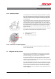
Accessories 7 Accessories 7.1 Additional clamping system for grinding harmful substances or in a gas atmosphere. The additional clamping system is used to transport a grinding bowl filled with inert gas or harmful substances from a glove box to the planetary mill and back again. This ensures that no harmful substances can be inhaled.
Accessories 2. Position the pressure plate with rubber disc on the bowl as shown in the picture. 3. When using grinding bowls with a volume of 80 ml, the adapter piece (90.1120.09) has to be used as well. NOTICE! Under no circumstances may 2 x 80 ml bowls be clamped on top of one another. This can lead to damage to the bowl and its component seals. 4. Then secure the pressure plate on both sides with the socket-head screws shown in the picture and a hex key. 5.
Accessories 6. The pressure piece has to be removed in order to use the SafeLock system for tensioning. 7. Clamp the additional clamping system with the Safe-Lock tensioning device into the device. 1. Position the bracket (a) of the clamping lever vertically! 2. Hang the longer projection of the Safe-Lock tensioning device into one side of the mounting of the grinding bowl holder. 3.
Accessories 4. Push the Safe-Lock tensioning device so that the mounting of the grinding bowl holder sits centrally in the U-shaped cut-out of the longer projection. 5. Pre-tension the setting screw (b) manually, and screw it tight using the provided torque spanner. Place the torque spanner on the setting screw (b) and turn until it clicks. 6. Then press the clamping lever downwards. Re-tighten the additional clamping system with a hex key.
Accessories We carry out a worker water bath test on all gassing lids. The part to be tested is sealed, a pressure of 5.5 bar is applied and it is immersed in a water bath. If there is a leak, bubbles will develop. The air bubbles that develop within a specific interval are evaluated by the worker/tester. Only gassing lids with a leak rate of <10‐4 [mbar l/s] are approved.
Accessories 7.2.2 Gassing n Slowly open the inert gas supply. n Press a thin object (e.g. hex key) onto the top of the ventilation attachment (e) so that the air can escape from the grinding bowl. n The inert gas now purges the air from the grinding bowl. n The duration of purging has to be determined through experimentation. It depends on grinding bowl size, filling, and gas supply, among other factors. n To end purging, close the inert gas supply and release the ventilation attachment.
Accessories 7.2.4 Cleaning the valves f g d Valve screwdriver Valve insert Valves Both valves (d) should be cleaned after every grinding! n Insert the thin end of the valve screwdriver (f) from above into the valve (d) and turn anti-clockwise. n Screw out the valve insert (g). n Depending on the soiling, clean the valve insert (g) with compressed air, or place it in a small glass container filled with alcohol and clean in an ultrasonic cleaner (LABORETTE 17) and then dry carefully.
Accessories NOTICE! The grinding parts made of agate are only designed for temperatures of up to 100 °C. After this point, they need to be slowly and carefully cooled down. 7.3 GTM - system The GTM system is available as an accessory for recording pressure and temperatures in the grinding bowl during grinding. Instructions are included with the GTM system.
Cleaning 8 Cleaning DANGER! Mains voltage! – Before beginning with cleaning work, disconnect the mains plug and protect the device against being unintentionally switched back on! – Do not allow any liquids to flow into the device. – Indicate cleaning work with warning signs. – Put safety equipment back into operation after cleaning work.
Maintenance 9 Maintenance DANGER! Mains voltage – Before beginning with maintenance work, unplug the mains plug and protect the device against being unintentionally switched back on again! – Indicate maintenance work with warning signs. – Maintenance work may only be performed by specialised personnel. – Put safety equipment back into operation after maintenance or repair work. We recommend keeping a safety logbook Ä Chapter 15 ‘Safety logbook’ on page 62, where all work (maintenance, repairs......
Maintenance Functional part Task or description Test Maintenance interval Drive motor Permanent lubrication Bearing clearance Every 4,000 h or annually V-belt Motor planetary disc Check belt tension Once a year Disconnect the device from the mains. Screw off the (top) rear cover plate. The belt must not slacken by more than 10 mm when pushed with your thumb.
Repairs 10 Repairs DANGER! Mains voltage! – Before beginning with repair work, unplug the mains plug and protect the device against being unintentionally switched back on. – Indicate repair work with warning signs. – Repair work may only be performed by specialised personnel. – Put safety equipment back into operation after maintenance work. 10.1 Checklist for troubleshooting Fault description Cause Remedy Mill does not start up No mains connection Plug in mains plug.
Repairs Fault description Grinding stock escapes Runs unevenly with strong vibrations Cause Remedy No mains connection Plug in mains plug. Main switch (10) at 0 (OFF) Switch on main switch (I). Device fuse Check device fuse; fuse insert on the back side of device 2 x 10 A T (12). Tensioning device (5) loose Check and re-tension if necessary. Seal ring is soiled or defective Clean or replace seal ring. Masses balanced inadequately Set mass balance more adequately: See Ä Chapter 6.
Examples of comminution tasks 11 Examples of comminution tasks Material Feeding amount Material of grinding bowl and balls Grinding balls, St.
Examples of comminution tasks Raw phosphate 40 g Cr steel 15 x 20 mm 100% 3 mm 250 ml 2 min < 250 µm Manganese dioxide MnO2 (wet grinding in water) 50 g / 40 ml water WC + Co 15 x 20 mm 100% 0.1 mm 250 ml 60 min < 20 µm 180 g Al2O3 10 x 30 mm 100% 8 mm 500 ml 30 min < 250 µm Sludge (dry) Active carbon (wet grinding in water) 150 ml Cr-Ni steel 15 x 20 mm 100% 0.
Disposal 12 Disposal It is hereby confirmed that FRITSCH has implemented the directive 2002/95/EC of the European Parliament and Council from 27th January 2003 for the limitation of the use of certain dangerous substances in electrical and electronic devices.
Guarantee terms 13 Guarantee terms Guarantee period As manufacturer, FRITSCH GmbH provides – above and beyond any guarantee claims against the seller – a guaranty valid for the duration of two years from the date of issue of the guarantee certificate supplied with the device. Within this guarantee period, we shall remedy all deficiencies due to material or manufacturing defects free of charge. Rectification may take the form of either repair or replacement of the device, at our sole discretion.
Guarantee terms Costs not covered by the guarantee This guarantee excludes any costs for transport, packaging or travel that accrue in the event the product must be sent to us or in the event that one of our specialist technicians is required to come to your site. Any servicing done by persons not authorised by us and any use of parts that are not original FRITSCH accessories and spare parts will void the guarantee.
Exclusion of liability 14 Exclusion of liability Before using the product, be sure to have read and understood this operating manual. The use of the product requires technical knowledge; only commercial use is permitted. The product may be used exclusively within the scope of applications set down in this operating manual and within the framework of guidelines put forth in this operating manual and must be subject to regular maintenance.
Exclusion of liability Fritsch GmbH excludes any liability, warranty, or other obligation to compensate for damages, regardless of whether this liability, warranty, or other obligation is explicit or implicit, contractual or arising from unlawful acts or prescribed contractually, by law, or otherwise.
Safety logbook 15 Date Safety logbook Maintenance / Repair Name - 62 - Signature
Safety logbook Date Maintenance / Repair Name - 63 - Signature
Safety logbook Date Maintenance / Repair Name - 64 - Signature
Index 16 Index A N Accident prevention . . . . . . . . . . . . . . . . . . . . . . . . 8 Additional clamping system . . . . . . . . . . . . . . . . . . 42 Adjusting to the mains voltage . . . . . . . . . . . . . . . 23 Authorised persons . . . . . . . . . . . . . . . . . . . . . . . . 8 Number of balls per bowl . . . . . . . . . . . . . . . . . . . 30 O Opening the hood without mains connection . . . . . 14 Operating noise . . . . . . . . . . . . . . . . . . . . . . . . . . 18 Operating principle . .
Index Weight . . . . . . . . . . . . . . . . . . . . . . . . . . . . . . . . 18 Wet grinding . . . . . . . . . . . . . . . . . . . . . . . . . . . .
© 2014 Fritsch GmbH Milling and Sizing Industriestraße 8 D - 55743 Idar-Oberstein Telephone: +49 (0)6784/ 70-0 Fax: +49 (0)6784/ 70-11 email: info@fritsch.de Internet: www.fritsch.