Operating Manual translation of the original FRITSCH Power Cutting Mill
PULVERISETTE 25 PULVERISETTE 25
PULVERISETTE 25 Fritsch GmbH Milling and Sizing Industriestrasse 8 D - 55743 Idar-Oberstein Phone: Fax: E-Mail: URL: +49 (0)6784/ 70-0 +49 (0)6784/ 70-11 info@fritsch.de http://www.fritsch.de Fritsch GmbH, Laborgerätebau has been certified by the TÜVZertifizierungsgemeinschaft e.V. Certificat registration number 71 100 J 596. It was verified through an audit that Fritsch GmbH satisfies the requirements of DIN EN ISO 9001:2008.
PULVERISETTE 25 Table of contents page 1 General Information / Introduction............................................................................................ 5 1.1 1.2 1.3 1.4 Basic Design..........................................................................................................................................5 Notes about Operating Instructions .......................................................................................................
PULVERISETTE 25 4 Working with the Cutting Mill .................................................................................................. 18 4.1 Preparation for Grinding ......................................................................................................................18 4.1.1 Opening the Cutting Mill ........................................................................................................................... 18 4.1.2 Inserting / Changing the Stationary Knives ....
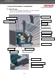
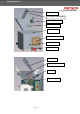
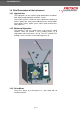
PULVERISETTE 25 1 General Information / Introduction 1.1 Basic Design The terms and numbering listed below are used to designate specific parts throughout this operating manual.
PULVERISETTE 25 (16) funnel lid (17) clamp safety switches (17) safety switches r (1) standard funnel (14) motor cover (18) ventilation louver (19) main switch (20) mains plug (21) funnel lid (22) protected funnel (23) piston (24) sample pusher page 6
PULVERISETTE 25 1.2 Notes about Operating Instructions x The copyright to these technical documents is the property of Fritsch GmbH, Manufacturers of Laboratory Instruments. x These operating instructions are not to be reprinted or copied without the express approval of Fritsch GmbH. x Please study these instructions carefully before attempting to operate the machine. x All operators must be familiar with the contents of the operating instructions. x Please observe all notes concerning your safety.
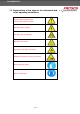
PULVERISETTE 25 1.3 Explanations of the signs at the instrument and in the operating instructions Attention! Warning against danger spot. Observe operating instructions. Attention! Mains voltage. Attention! Risk of explosion. Attention! Hot surface. Attention! Inflammable substances. Attention! Danger of crushing or pinching.
PULVERISETTE 25 1.4 Brief Description of the Instrument 1.4.1 Applications The cutting mill can be used for rapid comminution of mediumhard, brittle, tough and fibrous materials such as: sheet rubber, plastics, metal-free waste, dried meat, dried meat, leather, wood, coal, malt, paper/cardboard, peat, animal fodder, pasta, tablets, leaves, pellets, spices, fabric, straw, maize, bones, roots, tobacco ... 1.4.2 Method of Operation The material is fed via a feed funnel (1,22) into the cutting chamber.
PULVERISETTE 25 1.5 Technical Data 1.5.1 Dimensions 450 mm x 650 mm x 630 mm (width x depth x height) 1.5.2 Weight x 75 kg (net weight) x 105 kg (gross weight) 1.5.3 Noise level The noise level is approx. 71dB (A) at idle. The value fluctuates considerably depending on the material being ground. 1.5.
PULVERISETTE 25 2 Operating Safety 2.1 General Safety Instructions x Read the operating instructions carefully before use. x The instrument can only to be used for the purpose described in Chapter 1.4.1 Applications. x Use only original accessories and original spare parts. Failure to do so may call into question the performance of the instrument. x Do not use damaged accessories. x The operators must be familiar with the contents of the operating instructions.
PULVERISETTE 25 2.3 Protective Equipment x Protective equipment must be used as intended and must not be rendered disabled or dismantled. x All protective devices should be regularly checked for completeness and to ensure that they are functioning correctly. x The cutting mill is equipped with a safety lock for personal protection, which locks the front cover flap (6) during operation.
PULVERISETTE 25 2.4 Danger Points x x x x x The cover flap (6) can be lifted out of the hinges. When opening up the upper housing (2), it is possible to leave the cover flap (6) in the hinge. If this is the case, it is important to ensure that the cover flap (6) is not lifted out of the hinge while the upper housing (2) is opened. An initial resistance will be felt when the upper housing (2) is being opened.
PULVERISETTE 25 2.5 Electrical Safety 2.5.1 General x x Press the STOP button: the cutting mill will slow down and stop. Set the main switch (19) on the back side of the cutting mill to 0 (OFF) if the instrument will not be operated for an extended period (e.g. over night). 2.5.2 Protection against Restarting In the event of a mains failure during operation or after the machine has been switched off with the main switch (19), the cover flap (6) will remain locked.
PULVERISETTE 25 3 Installation 3.1 Unpacking x Remove the nails with which the protective packing is fastened on the transport pallet. x Lift the hood off the transport pallet. x Check that the items supplied correspond to your order before proceeding. 3.2 Transport x Transport the machine on the transport pallet using a fork lift truck or hand fork lift truck. x To carry the machine, grip it below at the front and the back. Do not use the housing for carrying.
PULVERISETTE 25 3.5 Ambience conditions x x x x x Use the instrument only inside. The air must not contain any electrical conductive dust. The ambient temperature must be between 5 and 40°C. Height up to 2000m M.S.L. Maximum relative humidity of air 80% temperature up to 31qC, linear decreasing down to 50% relative humidity of air at 40qC x Contamination level 2 (IEC 664) 3.
PULVERISETTE 25 3.8 Switching On for the Test for Correct Functioning First Time / First switch the instrument on when all of the tasks described in the Chapters 3.1 to 3.7have been carried out! 3.8.1 Switching On 1. 2. 3. 4. 5. Again check that the cutting mill is located securely. Check whether the funnel (1,22) is firmly mounted and closed. Insert the collecting vessel (8). Check whether the latch clamp (13) is closed.
PULVERISETTE 25 4 Working with the Cutting Mill 4.1 Preparation for Grinding 4.1.1 Opening the Cutting Mill 1. Set the main switch (19) on the back of the instrument to I (ON). 2. Unlock the latch clamps (13). 3. Open the cover flap (6). It is possible to lift the cover flap (6) out of the hinge after opening it. However, this is only required for the purpose of cleaning, for example. 4. Slowly swing open the upper housing (2) until it rests against the rubber stop. 4.1.
PULVERISETTE 25 4.1.2.1 Stationary Knife Positions 45.7180.09 45.7181.09 (9) Stationary knife 3 45.7160.09 45.7161.09 (4) Stationary knife 1 45.7170.09 45.7171.09 (5) Stationary knife 2 4.1.2.2 Stationary Knife Positions with TC-Equipped Blade 45.7330.00 (9) Stationary knife 3 45.7310.00 (4) Stationary knife 1 45.7320.00 (5) Stationary knife 2 Important!! Note the position of the TC hard metal strips. These are marked in BLUE in the image above.
PULVERISETTE 25 4.1.3 Setting the Knife Gap Width The factory setting for the knife gap is approx. 0.5 mm. 1. Open the Cutting Mill (see chapter 4.1.1) 2. Loosen the middle mounting screws on all 3 stationary knives (4,5,9) and unscrew them partially. Mounting screw (A) for fastening and loosening the stationary knives when adjusting the knife gap width. Threaded rods (B) for adjusting the cutting gap. 3.
PULVERISETTE 25 4.1.4 Inserting / Changing a Rotor 1. Open the cutting mill (see chapter 4.1.1) 2. Pull the rotor (3) out to the front while wearing protective gloves. If the rotor (3) sticks somewhat, carefully leverage it out. 3. Clean the tapered mounts for the rotor (3). 4. Clean both tapered mounts (cones) in the cover flap (6) and on the mount. 5. Slide the rotor (3) onto the rotor mount. Turn it clockwise until the back side clicks into place on the 4 drive pins (4).
PULVERISETTE 25 C 6. Close the cutting mill (see chapter 4.1.6) Caution! Check whether the rotor (3) turns freely (see chapter Fehler! Verweisquelle konnte nicht gefunden werden.). If this is not the case, do as described in chapter 4.1.3 Setting the Knife Gap Width Perform this check every time the rotor (3) is changed! 4.1.5 Inserting / Changing a Sieve Cassette 1. Open the cutting mill (see chapter 4.1.1) 2. Pull out the sieve cassette (7) to the front; the rotor (3) does not have to be removed.
PULVERISETTE 25 4.1.6 Closing the Cutting Mill 1. Before closing the cutting mill, clean the cutting chamber, the contact surfaces of the housing, and in particular the closing surfaces of the lock. 2. Slowly swing the upper housing (2) closed until it rests on the housing base (10). 3. Close the cover flap (6). 4. Latch clamp (13) lock. 5. Set the main switch (19) on the back of the instrument to 0 (OFF). 6.
PULVERISETTE 25 5. Unscrew the 3 screws holding the motor cover (14) in place. 6. Carefully push back the motor cover (14). 7. Disconnect the standard funnel (1) from terminals 2 and 2.1. 8. Fasten the cable link S4 to terminals 2 and 2.1.
PULVERISETTE 25 9. Pull the funnel cable out of the angled screw coupling by sliding the clamping ring down and pulling the black cable guide out of the angle coupling. 10.Unscrew the angled screw coupling from the motor cover and close the hole with a cap. Screw this in with a screwdriver. 11.Position the motor cover (14) and screw it on. 12.
PULVERISETTE 25 4.1.7.3 Changing from the Protected Funnel to the Standard Funnel 1. Close the cutting mill. 2. Close the funnel lid (21). 3. Set the main switch (19) on the back of the instrument to 0 (OFF). 4. Unplug the mains plug (20). 5. Use an Allen key to unscrew the four M6x12 cheese head screws with which the protected funnel (22) is fastened to the upper housing (2) and lift off the protected funnel (22). 6.
PULVERISETTE 25 8. Carefully push back the motor cover (14). 9. Use a screwdriver to unscrew the cap covering the opening for running the funnel cable through. 10.Pull off the angled screw coupling located on the funnel cable (push the clamping ring down) and screw it into the motor cover. 11.Then run the funnel cable through the screw coupling to inside the instrument. 12.If the cable sticks, do as follows (see circuit diagrams in the service manual): x Remove the cable link S4 from terminals 2 and 2.
PULVERISETTE 25 x Connect the funnel cable to terminals 2 and 2.1. 13. Position the motor cover (14) and screw it on. 14.Reconnect the cutting mill to the mains. 15.Set the main switch (19) on the back of the instrument to I (ON). 16.Check the functioning of the funnel. The cutting mill may only start up while the funnel lid (16) is closed. When the funnel lid is opened, the mill must shut down automatically (see chapter 2.3). 17.The instrument is ready for operation. 4.
PULVERISETTE 25 4.3 Grinding Process with the Protected Funnel 1. 2. 3. 4. 5. 6. Set the main switch (19) on the back of the instrument to I (ON). Close the cutting mill (see chapter 4.1.6). Insert the collecting vessel (8). Pull out the sample pusher (24) fully. Move the piston (23) into the lower position. Open up the funnel lid (21), add some grinding material and close the lid again. The quantity of material to be ground will depend on the feed grain size and the grindability of the material.
PULVERISETTE 25 4.4 Overloading of the Cutting Mill During loading and during the downwards movements of the piston (23), attention should be paid to the noise of the grinding process. The volume of the noise corresponds very closely to the loading of the machine. It is also clear from the sound pitch if the motor speed is decreasing due to overloading.
PULVERISETTE 25 7. Position the motor cover (14) and screw it on. 8. Reconnect the cutting mill to the mains. 9. Set the main switch (19) on the back of the instrument to I (ON). 10.The Start button lights green. 11.The instrument is ready for operation. 5 Cleaning 5.1 Housing The cutting mill can be wiped clean with a damp cloth while switched off (main switch (19) set to 0 (OFF)). Do not allow any liquids to flow into the device. 5.
PULVERISETTE 25 5.3.2 Protected Funnel (22) 1. Set the main switch (19) on the back of the instrument to 0 (OFF). 2. Pull the sample pusher (24) out of the funnel (22) up to the stop and fix it in place with the knurled screw (A). 3. Open the funnel lid (21). 4. Clean the protected funnel (22) from above. a 5. Close the funnel lid (21). 6. Pull the piston (23) out of the funnel (22) up to the stop and fix it in place with the knurled screw (B). 7. Open the cutting chamber as described above. 8.
PULVERISETTE 25 5.3.2.2 Removing the Piston (23): 1. Open the funnel lid (21). 2. Use a screwdriver to unscrew the Phillips head screws (D). D 3. Close the funnel lid (21). 4. Use a screwdriver to unscrew the Torx screws (E). E b 5. Unscrew the knurled screw (B). 6. The piston (23) can be taken out. 23 7. Reinstall in reverse order. 5.4 Collecting Vessel Pull out and clean the collecting vessel (8). It can be vacuumed out or wiped with a damp cloth.
PULVERISETTE 25 6 Maintenance During maintenance work that does not require a power supply, unplug the mains plug (20) and secure the instrument against unauthorised reactivation before starting the work! Warn about maintenance work with a sign. Regular cleaning is (chapter 5) the most important maintenance function for the cutting mill. (A) filter holder (B) foam mat (25) filter Functional part Task Test Filter of the cutting mill (25) Filtering exhaust air Clean the air filter (25).
PULVERISETTE 25 page 35
PULVERISETTE 25 page 36
PULVERISETTE 25 7 Warranty The warranty card enclosed with the device upon delivery must be completely filled out and returned to the delivering factory so that the warranty can enter into effect. Online registration is also possible. More information can be found on your warranty card or on our website http://www.fritsch.
PULVERISETTE 25 9 Disclaimer Before using this product, these operating instructions are to be carefully read and be understood. Use of the product requires expertise and it is to be carried out only by commercial users. The product may be used exclusively for the applications outlined in these instructions and within the scope of the regulations set out in these operating instructions, and it shall subject to regular maintenance.
PULVERISETTE 25 Fritsch GmbH expressly disclaims every explicit or implied, contractual or arising from improper handling or a fixed contractual, statutorial or other liability, warranty or other obligation in respect of compensation obligations. Under no circumstances shall Fritsch GmbH accept liability, resp.
PULVERISETTE 25 10 List of keywords A Applications ............................................... 9 D Danger Points.......................................... 13 direction of rotation.................................. 14 E electrical connection................................ 16 electrical safety........................................ 14 M main switch.............................................. 35 maintenance............................................ 34 O overloading...................................
PULVERISETTE 25 PULVERISETTE 25
PULVERISETTE 25 PULVERISETTE 25
PULVERISETTE 25