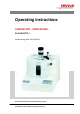
Operating instructions LABORATORY - MORTAR MILL PULVERISETTE 2 Valid starting with: 02.
Fritsch GmbH Milling and Sizing Industriestraße 8 D - 55743 Idar-Oberstein Telephone: +49 (0)6784/ 70-0 Fax: +49 (0)6784/ 70-11 email: info@fritsch.de Internet: www.fritsch.
Certifications and CE conformity Certifications and CE conformity Certification Fritsch GmbH has been certified by the TÜV-Zertifizierungsgemeinschaft e.V. An audit certified that Fritsch GmbH conforms to the requirements of the DIN EN ISO 9001:2008. CE Conformity The enclosed Conformity Declaration lists the guidelines the FRITSCH instrument conforms to, to be able to bear the CE mark.
Table of contents Table of contents 1 Basic structure............................................................................... 6 2 Safety information and use........................................................... 7 2.1 Requirements for the user..................................................... 7 2.2 Scope of application............................................................... 7 2.2.1 Operating principle............................................................. 8 2.
Table of contents 6.3.1 Installing/removing the mortar........................................ 6.3.2 Installing/removing the pestle.......................................... 6.3.3 Mounting the scraper....................................................... 6.4 Setting the grinding pressure............................................... 6.4.1 Positioning the pestle against the bottom of the mortar. 6.4.2 Positioning the pestle against the mortar wall................. 6.4.
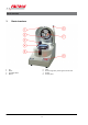
Basic structure 1 1 2 3 4 Basic structure Lid Pestle Lid safety switch Mortar 5 6 7 8 -6- Latch Pressure regulator, pestle against mortar wall Scraper Control panel
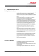
Safety information and use 2 Safety information and use 2.1 Requirements for the user This operating manual is intended for persons assigned with operating and monitoring the Fritsch PULVERISETTE 2. The operating manual and especially its safety instructions are to be observed by all persons working on or with this device. In addition, the applicable rules and regulations for accident prevention at the installation site are to be observed.
Safety information and use 2.2.
Safety information and use 2.3 Obligations of the operator Before using the PULVERISETTE 2, this manual is to be carefully read and understood. The use of the PULVERISETTE 2 requires technical knowledge; only commercial use is permitted. The operating personnel must be familiar with the content of the operating manual. For this reason, it is very important that these persons actually receive the present operating manual. Ensure that the operating manual is always near the device.
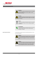
Safety information and use WARNING! This symbol and keyword combination points out a possibly hazardous situation that can result in death or serious injury if not avoided. CAUTION! This symbol and keyword combination points out a possibly hazardous situation that can result in slight or minor injury if not avoided. NOTICE! This symbol and keyword combination points out a possibly hazardous situation that can result in property damage if not avoided.
Safety information and use DANGER! This symbol and keyword combination designates contents and instructions for proper use of the machine with combustible substances. Ignoring information with this designation will result in serious or fatal injury. WARNING! This symbol and keyword combination points out a directly hazardous situation due to movable parts. Ignoring information with this designation can result in hand injuries.
Safety information and use Designation Explanation Step-by-step procedure instructions 1., 2., 3. ... ð Results of steps in the procedure References to sections in this manual and relevant documentation Lists without a specific order [Button] Operating elements (e.g. push button, switch), display elements (e.g. signal lamps) ‘Display’ Screen elements (e.g. buttons, function key assignment) 2.5 Device safety information Please observe! n Only use original accessories and original spare parts.
Safety information and use DANGER! Explosion hazard! – When grinding oxidizable substances, e.g. metals or coal, there is a risk of spontaneous combustion (dust explosion) if the share of fine particles exceeds a certain percentage. When grinding these kinds of substances, special safety measures must be taken and the work must be supervised from a specialist. – The PULVERISETTE 2 is not explosion protected and is not designed to grind explosive materials. n Do not remove the information signs.
Safety information and use 2.7 Hazardous points CAUTION! – Crushing hazard when closing the grinding chamber! – Crushing hazard when closing the latch (5)! – Crushing hazard when inserting the mortar! 2.8 Electrical safety n The main switch on the back of the device separates the device from the mains on two poles. 2.8.
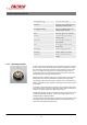
Technical data 3 Technical data 3.1 Dimensions 410 x 310 x 460 mm (height x width x depth) 3.2 Weight 24 kg (net) 34 kg (gross) 3.3 Operating noise Emissions value of workplace according to DIN EN ISO 3746:2005 LPa = 49.5 dB(A). The noise level measurement was conducted with feed pellets as grinding stock and grinding elements made of agate! 3.
Technical data 3.8 Final fineness The final fineness depends on the grinding duration - sufficiently long grinding times can yield an average particle feed size of 10 µm.
Installation 4 Installation 4.1 Transport WARNING! Improper lifting can lead to personal injury or property damage. The machine must only be lifted with suitable equipment by qualified personnel. The device is delivered on a transport pallet with a wooden hood or in a cardboard box. The guarantee excludes all claims for damage due to improper transport. 4.2 Unpacking n Pull out the nails that fasten the hood to the transport pallet.
Installation 4.4 Ambient conditions WARNING! Mains voltage! – The device may only be operated indoors. – The surrounding air may not carry any electrically conductive dust. – Maximum relative humidity 80% for temperatures up to 31°C, linearly decreasing down to 50% relative humidity at 40°C. n The room temperature has to stay between 5 - 40°C. n Altitudes up to 2000 m n Degree of pollution 2 according to IEC 664. 4.
Initial start-up 5 Initial start-up Perform initial start-up only after all work as described in Ä Chapter 4 ‘Installation’ on page 17 has been carried out. 5.1 Switching on 1. Connect the device to the mains. 2. Switch on the device using the mains switch (on the back of the device). 3. The display of the digital timer lights up red. 1. Close the hood. 2. The laboratory mortar mill starts to work as soon as the START button is pressed. 1. Press the STOP button. 2.
Using the device 6 Using the device WARNING! If the grinding elements used are not original accessories, we provide no guarantee and exclude all liability for damage to the device. The laboratory mortar mill only works/starts with the lid closed. The device shuts down if the lid is opened during operation. The device cannot be started with the lid open. 6.1 Timer After starting the device (main switch on the back of the device), the timer shows the time setting of the preceding grinding process.
Using the device 6.1.3 Setting the grinding duration The desired grinding duration can be set with the " + " and " - " buttons. Depending on the set operating mode, the display indicates hours/ minutes or minutes/seconds. 6.1.4 Grinding mode/Grinding stop The START button starts the grinding process (only if the lid is closed). The display indicates the remaining time of the grinding process. When the grinding time has elapsed, the preset time is displayed again.
Using the device NOTICE! If liquid nitrogen is added to the grinding process, it is only permitted with the monolithic stainless-steel grinding set. With mineral materials, there is a great risk of damaging the grinding elements by adding liquid nitrogen. Grinding with mineral grinding elements and added liquid nitrogen will void the guarantee. 6.3 Installing / removing the grinding set The grinding parts used in the laboratory mortar mill are made so that the scraper and mortar fit together exactly.
Using the device Note n Rotation to the right = clockwise rotation n Rotation to the left = anticlockwise rotation An arrow on the mortar indicates the direction of rotation of the mill. Rotate the mortar in the direction of the arrow to open the bayonet. 6.3.2 Installing/removing the pestle The pestle is held in place with a catch holder and can be easily removed without tools. Pull the pestle in the direction of its axis to release it from the catch holder.
Using the device 6.4 Setting the grinding pressure NOTICE! Before commissioning, it is necessary to adjust (zero position) the pressure scale (see Ä Chapter 6.5.1 ‘Adjusting’ on page 25). The contact pressure of the pestle against the wall and bottom of the mortar must be adjusted in two directions. The contact pressure is adjusted with the lid and latch closed. 6.4.
Using the device 6.4.3 Pre-crushing settings for coarse samples To pre-crush coarse samples of up to 8 mm, the adjusting nut (c) can be raised above the zero position if necessary so that coarse particles fit below the pestle and can be comminuted. (see the illustration under Ä Chapter 6.4.1 ‘Positioning the pestle against the bottom of the mortar’ on page 24) For subsequent fine grinding, the pestle is lowered again to the desired position. (Set to contact pressure [daN Downforce] between 2.5 - 17.
Using the device The zero position of the pressure scale can be determined two different ways: n Close the lid and its latch. Start the device (START). The adjusting nut (c) is now used to slowly lower the pestle until it touches the bottom of the rotating mortar. When observing the pestle, it is possible to see that the pestle is moved by the contact with the mortar. The scale is now loosened (see illustration) and shifted so that it displays the zero position of the pestle.
Using the device 6.6.1 Setting the scraper 1. Turn the screw to the left. 2. Release the lever. 3. Grip the guide rod. 4. Move the scraper against the wall and onto the bottom of the mortar by turning it to the left. Turn the screw downward until it rests on the rocker element.
Using the device 5. Tilt the guide rod while turning the scraper to the left to align it with the guide rod. 6. Clamp the lever. Then release the guide rod. 7. Turn the screw to the right to reduce the contact pressure of the scraper against the mortar so that the scraper lightly touches the wall. It is advisable to adjust the scraper during grinding to check the correct position of the scraper according to the movement of the grinding stock.
Using the device 6.7 Filling the grinding stock / Starting the grinding process 1. Open the latch of the lid. Open the laboratory mortar mill. 2. Fill a maximum of 190 ml grinding stock (particle feed size < 8 mm) into the front area of the mortar. 3. Close the lid of the mill. Secure the lid by closing the latch. 4. Set the desired contact pressure. Standard setting for most samples: 10-15 daN and lateral contact pressure; the first ring is visible. 5. Set the desired grinding duration. 6.
Using the device NOTICE! If liquid nitrogen is added to the grinding process, it is only possible when using the stainless steel grinding set (order no. 462140.00) because the mortar is manufactured from solid material (monolithic). All other grinding sets have a plastic casing, which would be destroyed by adding liquid nitrogen. The grinding set must be cooled down with liquid nitrogen outside of the PULVERISETTE 2 beforehand. This helps prevent nitrogen from boiling inside the device.
Cleaning 7 Cleaning DANGER! Mains voltage! – Before beginning with cleaning work, disconnect the mains plug and protect the device against being unintentionally switched back on! – Do not allow any liquids to flow into the device. – Indicate cleaning work with warning signs. – Put safety equipment back into operation after cleaning work.
Cleaning Should it be necessary to use the seal, but there are prob‐ lems with abrasion of the seal (possible with samples which produce large amounts of dust or hot grinding stock), we recommend using the included lubricant.
Maintenance 8 Maintenance DANGER! Mains voltage – Before beginning with maintenance work, unplug the mains plug and protect the device against being unintentionally switched back on again! – Indicate maintenance work with warning signs. – Maintenance work may only be performed by specialised personnel. – Put safety equipment back into operation after maintenance or repair work. We recommend keeping a safety logbook Ä Chapter 13 ‘Safety logbook’ on page 41, where all work (maintenance, repairs......
Maintenance Functional part Task Test Maintenance interval Safety switch Operator safety Does the mill stop when the hood is opened? Before each use Ventilation slots Cooling system, electronics Proper function, Twice a year clean when soiled 8.3 Resharpening the grinding set After prolonged use, scratches or irregularities may appear on the surfaces of mortar and pestle, in which grinding stock can get stuck. It is possible to resharpen the grinding mortar by filling it with approx.
Repairs 9 Repairs DANGER! Mains voltage! – Before beginning with repair work, unplug the mains plug and protect the device against being unintentionally switched back on. – Indicate repair work with warning signs. – Repair work may only be performed by specialised personnel. – Put safety equipment back into operation after maintenance work. 9.
Disposal 10 Disposal It is hereby confirmed that FRITSCH has implemented the directive 2002/95/EC of the European Parliament and Council from 27th January 2003 for the limitation of the use of certain dangerous substances in electrical and electronic devices.
Guarantee terms 11 Guarantee terms Guarantee period As manufacturer, FRITSCH GmbH provides – above and beyond any guarantee claims against the seller – a guaranty valid for the duration of two years from the date of issue of the guarantee certificate supplied with the device. Within this guarantee period, we shall remedy all deficiencies due to material or manufacturing defects free of charge. Rectification may take the form of either repair or replacement of the device, at our sole discretion.
Guarantee terms Costs not covered by the guarantee This guarantee excludes any costs for transport, packaging or travel that accrue in the event the product must be sent to us or in the event that one of our specialist technicians is required to come to your site. Any servicing done by persons not authorised by us and any use of parts that are not original FRITSCH accessories and spare parts will void the guarantee.
Exclusion of liability 12 Exclusion of liability Before using the product, be sure to have read and understood this operating manual. The use of the product requires technical knowledge; only commercial use is permitted. The product may be used exclusively within the scope of applications set down in this operating manual and within the framework of guidelines put forth in this operating manual and must be subject to regular maintenance.
Exclusion of liability Fritsch GmbH excludes any liability, warranty, or other obligation to compensate for damages, regardless of whether this liability, warranty, or other obligation is explicit or implicit, contractual or arising from unlawful acts or prescribed contractually, by law, or otherwise.
Safety logbook 13 Date Safety logbook Maintenance / Repair Name - 41 - Signature
Safety logbook Date Maintenance / Repair Name - 42 - Signature
Safety logbook Date Maintenance / Repair Name - 43 - Signature
Safety logbook Date Maintenance / Repair Name - 44 - Signature
Index 14 Index A Installation . . . . . . . . . . . . . . . . . . . . . . . . . . . . . 17 Accident prevention . . . . . . . . . . . . . . . . . . . . . . . . 7 Adjusting the mains voltage . . . . . . . . . . . . . . . . . 18 Adjusting the vertical pressure scale . . . . . . . . . . . 25 Ambient conditions . . . . . . . . . . . . . . . . . . . . . . . 18 Authorised persons . . . . . . . . . . . . . . . . . . . . . . . . 7 M Maintenance . . . . . . . . . . . . . . . . . . . . . . . . . . Materials . .
Index WEEE . . . . . . . . . . . . . . . . . . . . . . . . . . . . . . . . . 36 Weight . . . . . . . . . . . . . . . . . . . . . . . . . . . . . . . . 15 Working with the device . . . . . . . . . . . . . . . . . . . .
© 2014 Fritsch GmbH Milling and Sizing Industriestraße 8 D - 55743 Idar-Oberstein Telephone: +49 (0)6784/ 70-0 Fax: +49 (0)6784/ 70-11 email: info@fritsch.de Internet: www.fritsch.